Confocal automatic regulation device

An automatic adjustment, confocal technology, applied in material excitation analysis, fluorescence/phosphorescence, etc., can solve the problem of poor repeat positioning of confocal detection device

Inactive Publication Date: 2014-06-04
BEIJING INSTITUTE OF TECHNOLOGYGY
View PDF6 Cites 6 Cited by
  • Summary
  • Abstract
  • Description
  • Claims
  • Application Information

AI Technical Summary

Problems solved by technology

[0004] The purpose of the present invention is to provide a confocal automatic adjustment device. According to the adjustment method, the automatic adjustment of the confocal device can be completed, and the problem of poor repeat positioning of confocal detection devices such as microfluidic chips can be solved.

Method used


Image

  • Confocal automatic regulation device
  • Confocal automatic regulation device
  • Confocal automatic regulation device

Examples


Embodiment Construction

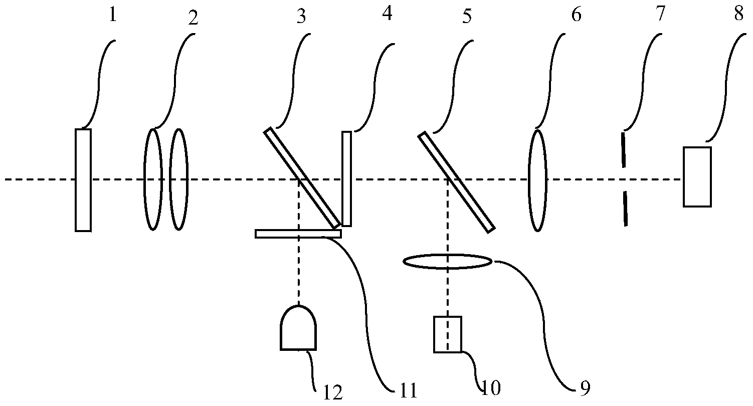
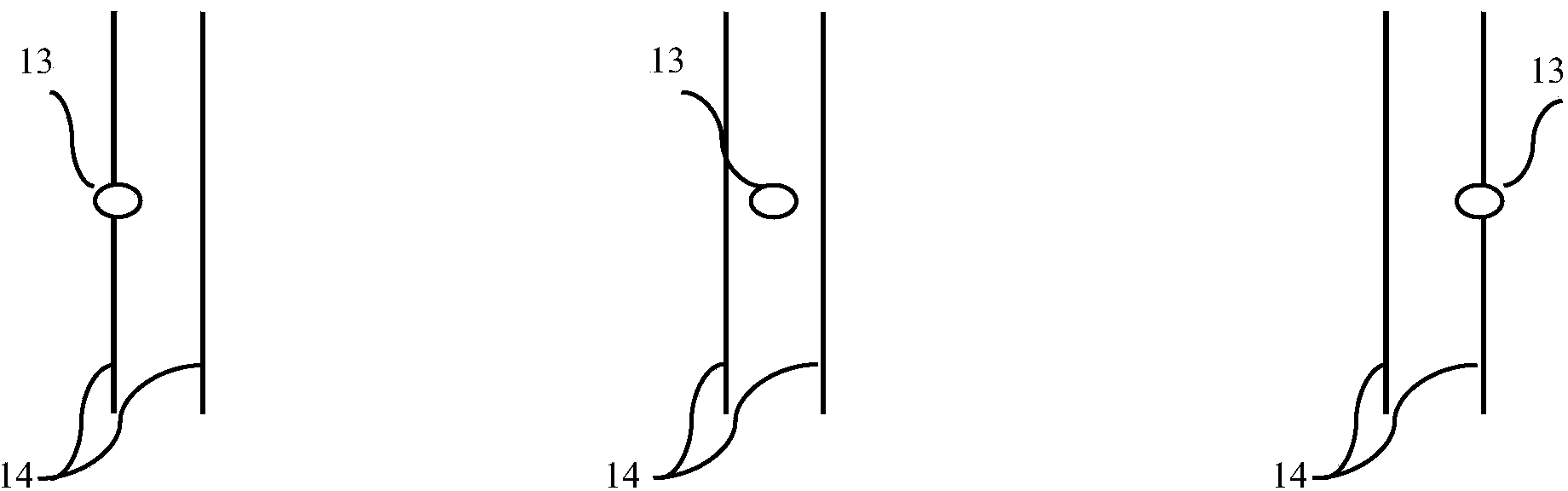
[0012] The present invention will be described in further detail below in conjunction with the accompanying drawings and examples. Here, the exemplary embodiments of the present invention and their descriptions are used to explain the present invention, but not to limit the present invention.

[0013] When (1) the microfluidic chip to be tested is placed on the stage, due to installation errors, the position of the focused spot of the (12) excitation light source through the (2) zoom objective lens cannot coincide with the center position of the detection channel, such as figure 2 As shown in the left or right image, it cannot coincide with the center of the detection channel along the optical axis, such as image 3 as shown in the left or right image.

[0014] After the device is started, first move the stage in the horizontal direction according to the image obtained by (9) monitoring lens group and (10) image sensor, so that the center of the focused spot is aligned with ...


PUM


Abstract

The invention relates to a confocal automatic regulation device and in particular relates to a device for acquiring fluorescent information of a sample to be detected by adopting a confocal mode. The device is used for micro-fluidic chips and the like. According to the device, images in a sample area and inducing fluorescent light intensity information are acquired through an image sensor so as to regulate related parameters of the device, so that an adverse effect caused by a position resetting error of the sample to be detected is compensated, and the consistency of the detector is guaranteed. In addition, according to the device, a varifocus objective serves as an objective lens in the system, so that the size of focusing spots can be adjusted according to the size of the detected sample, the detected size of the detected sample by the device is increased, and the application range of the system is widened. Moreover, the use frequency of an expensive piezoelectric ceramic displacement table by the system can be reduced, so that the use cost of a confocal detector is reduced.

Description

technical field [0001] The invention relates to a confocal automatic adjustment device, especially a device for obtaining fluorescence information of a sample to be detected in a confocal manner, such as a microfluidic chip. The device obtains the image of the sample area and the light intensity information of the induced fluorescence through an image sensor Adjust the relevant parameters of the device to compensate for the adverse effects caused by repeated positioning errors in the position of the sample to be detected and ensure the consistency of the detector. Background technique [0002] Confocal fluorescence detection technology is a commonly used technology in microfluidic chip optical detection technology. This technology uses the small hole at the focal point of the optical path to effectively prevent the interference of impurity signals on weak fluorescent signals, and greatly improves the sensitivity of the detector. However, due to the limitations of the microfl...

Claims


Application Information

Patent Timeline
IPC IPC(8): G01N21/64
Inventor 胡晓明张凤娟李勤曹群
Owner BEIJING INSTITUTE OF TECHNOLOGYGY
Why Eureka
Try Eureka