Three-dimensional direction angle measuring device and method using celestial body position as alignment calibration reference
A three-dimensional space, measuring device technology, applied in the direction of measuring device, measuring angle, mapping and navigation, etc., can solve the problem that observation instruments cannot achieve high-precision direction finding, etc., and achieve the effect of improving pointing accuracy, improving accuracy and wide application range.
- Summary
- Abstract
- Description
- Claims
- Application Information
AI Technical Summary
Problems solved by technology
Method used
Image
Examples
Embodiment 1
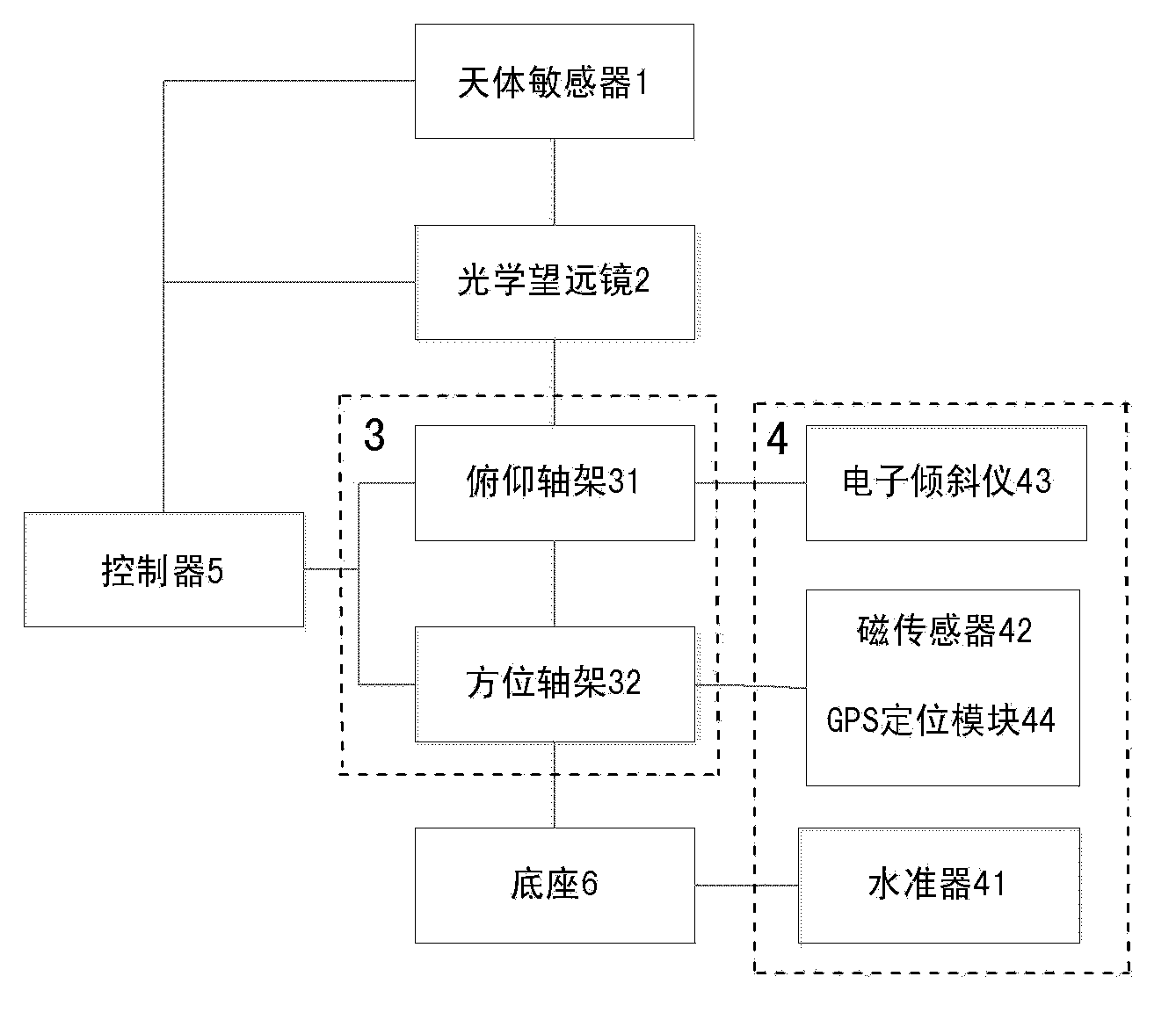
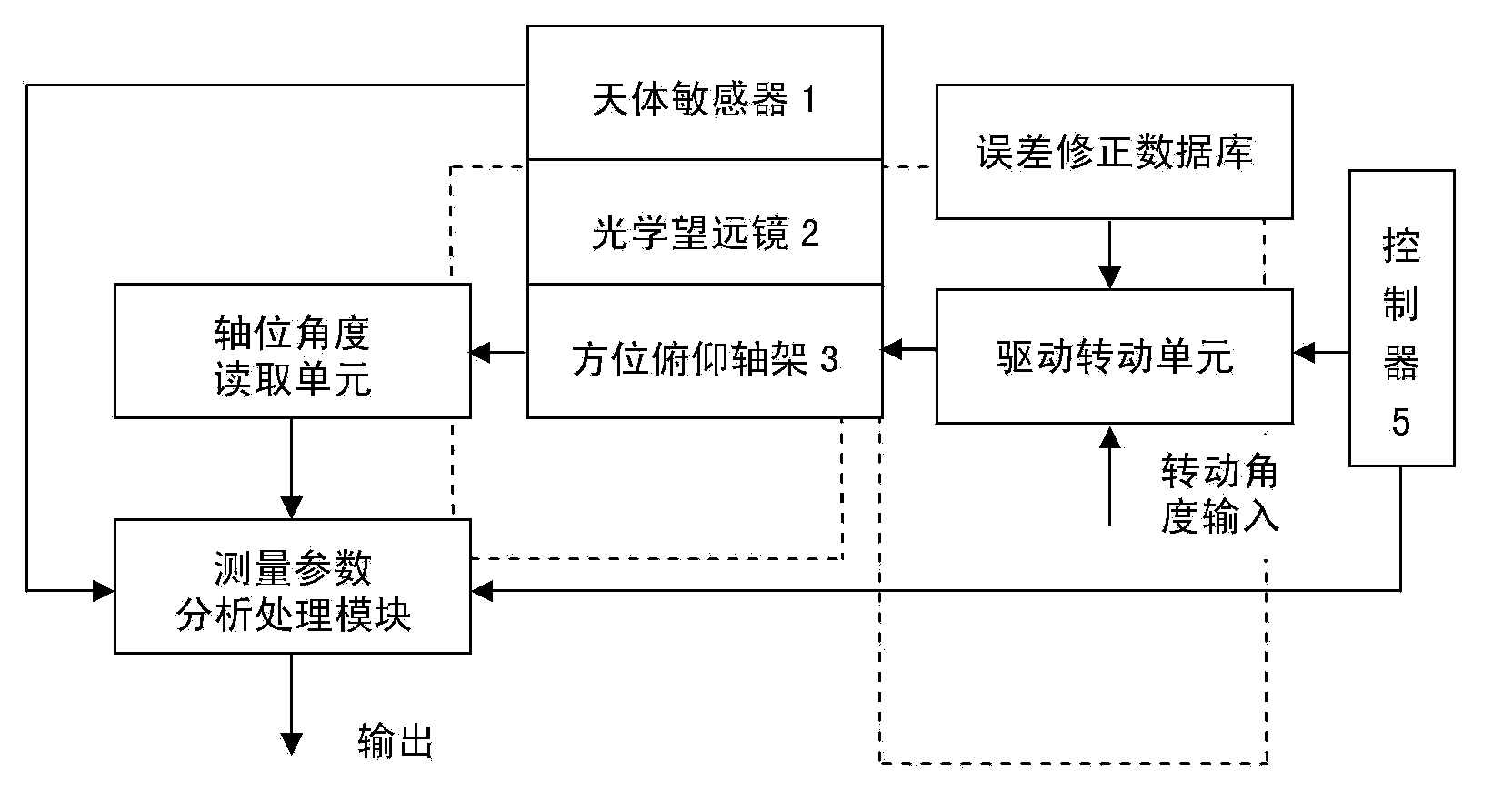
[0047] Such as figure 1 It shows a three-dimensional space direction angle measurement device that uses the position of celestial bodies as a standard for calibration. It is a three-dimensional space direction angle measurement device that uses the space positions of stars and planetary bodies as a measurement standard. The device uses stars and planets and other celestial bodies The position is used as the calibration and correction reference of the measurement, and the device is composed of a celestial body sensor 1, an optical telescope 2, an azimuth and pitch shaft frame 3, a plurality of sensors 4, a controller 5 and a base 6, wherein:
[0048] The azimuth and pitch shaft frame 3 includes a pitch shaft frame 31 and an azimuth shaft frame 32, and the pitch axis of the pitch shaft frame 31 and the azimuth axis of the azimuth shaft frame 32 are arranged orthogonally to each other; one end of the azimuth shaft frame 32 is placed in the base; The other end of the pedestal 32 i...
Embodiment 2
[0099] The three-dimensional space direction angle measuring device can simplify the composition of the device of the present invention, that is, the device of the present invention can be simplified into the form of a measurement component when the detected equipment already has a pitch axis, azimuth axis and axis position detection device. Direction angle measuring assembly 8 is only made up of celestial body sensor 1, controller 5 and GPS positioning module 44 etc. (referring to Figure 5 and Figure 8 ).
[0100] Only the celestial body sensor 1, the controller 5 and the GPS positioning module 44 form the azimuth measurement assembly, which is used to detect the azimuth angle in three-dimensional space for the monitored equipment that already has a pitch axis, azimuth axis and axis position detection display unit, At this time, the measurement assembly 8 is directly installed above the lens barrel of the optical telescope 2 on the pitch axis of the monitored equipment or ...
Embodiment 3
[0104] If the monitored equipment is a parabolic dish-shaped microwave antenna, at one end of the pitch axis of the parabolic dish-shaped microwave antenna, a three-dimensional space direction angle measurement assembly 8 can be used, and at one end of the pitch axis of the parabolic dish-shaped microwave antenna, the direction angle measurement assembly The conical shaft head with conical mating surface of 8 is inserted into the conical hole of the pitch shaft end, so that the matching conical surface A of the conical shaft head of the azimuth measurement component 8 and the conical hole of the pitch shaft end After installation, use clamp rings and screws to fasten them, or connect one side of the transition curve bracket 82 to an axis end of the pitch axis, and then fix the astrosensor 1 on the transition curve bracket 82 (see Figure 6 ). After installation, the pointing angle accuracy of the microwave antenna can be calibrated by using the position information of the cele...
PUM
 Abstract
Description
Claims
Application Information
 - R&D
- Intellectual Property
- Life Sciences
- Materials
- Tech Scout
- Unparalleled Data Quality
- Higher Quality Content
- 60% Fewer Hallucinations
Browse by: Latest US Patents, China's latest patents, Technical Efficacy Thesaurus, Application Domain, Technology Topic, Popular Technical Reports.
© 2025 PatSnap. All rights reserved.Legal|Privacy policy|Modern Slavery Act Transparency Statement|Sitemap|About US| Contact US: help@patsnap.com


