
Pile-forming device and method for vortex pressing extruding and expanding concrete layering expanding pile

A technology of concrete and expanded diameter piles, which is applied in the direction of sheet pile walls, buildings, and foundation structure engineering, etc., can solve the problems of pile necking, insufficient pressure, and insufficient self-weight of equipment, etc., to achieve improved vertical and horizontal strength, good fluidity, The effect of simple construction

Inactive Publication Date: 2014-12-10
CHINA UNIV OF PETROLEUM (EAST CHINA)
View PDF6 Cites 0 Cited by
  • Summary
  • Abstract
  • Description
  • Claims
  • Application Information

AI Technical Summary

Problems solved by technology

However, cast-in-place threaded piles often appear in engineering practice because when the bearing capacity of the soil is large, the self-weight or pressure of the equipment is insufficient, and the reaction force of the soil on the drilling tool is greater than the pressure of the drilling rig, causing the drill pipe to rotate in situ and "slip". At this time, the shear strength of the soil between the screw teeth will be destroyed. Although it looks like there are threads after the pile is formed, the soil between the screw teeth has been sheared, and it has become a straight pile without a variable diameter pile. due performance
During the retraction of the hydraulic pressure bearing plate and the pouring of concrete, the disc pile will easily cause the expansion part to collapse, resulting in necking of the pile body and mud inclusion, and becoming a waste pile

Method used


Image

  • Pile-forming device and method for vortex pressing extruding and expanding concrete layering expanding pile
  • Pile-forming device and method for vortex pressing extruding and expanding concrete layering expanding pile
  • Pile-forming device and method for vortex pressing extruding and expanding concrete layering expanding pile

Examples


Embodiment Construction

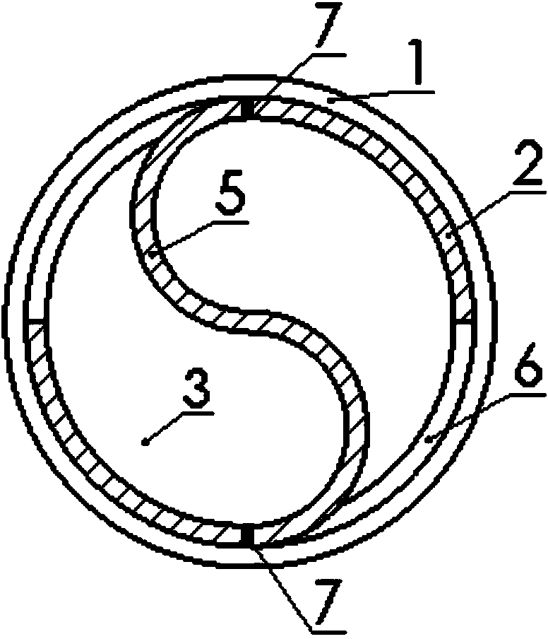
[0026] Such as figure 1 , figure 2 As shown, the pile-forming equipment of vortex squeezed and expanded concrete layered diameter-expanding piles includes: pile head 1, steel casing 2, rotating gear 4, radial vortex blade 5, axial vortex blade 8; pile head 1 It is arranged at the bottom of the steel sleeve, the rotating gear 4 is installed on the top of the steel sleeve 2, the radial scroll blade 5 is installed inside the opening of the steel sleeve, and the axial scroll blade 8 is located in the steel sleeve and installed on the diameter To the top of scroll blade 5; Wherein:

[0027] The pile head 1 is a prefabricated concrete structure, the upper part is a cylinder, the lower part is a cone, and the top of the cylinder forms a cylindrical boss.

[0028] The steel casing 2 is a metal round pipe, and the inner diameter of the steel casing 2 is slightly larger than the outer diameter of the cylindrical boss of the precast concrete pile head 1, so as to ensure that the top o...


PUM


Abstract

The invention belongs to the field of geotechnical engineering, and particularly relates to a pile-forming device and method for a vortex pressing extruding and expanding concrete layering expanding pile. The device for the vortex pressing extruding and expanding concrete layering expanding pile comprises a pile head, a steel sleeve, a rotation gear, a radial vortex pressing blade and an axial vortex pressing blade. The pile head is arranged at the bottom of the steel sleeve, the rotation gear is installed on the top of the steel sleeve, the radial vortex pressing blade is installed on the inner side of an opening of the steel sleeve, and the axial vortex pressing blade is installed on the top of the radial vortex pressing blade. The steel sleeve can be recycled, construction is easy, original soil does not need to be excavated, the construction time is shortened, and the manufacturing cost is reduced. The longitudinal and transverse strength of a soil body can be greatly improved, and the expanding part can play an end bearing role. The method is high in applicability and suitable for various sand soil and viscidity soil. According to the method, layering expanding can be carried out, and the key problem that quality cannot be guaranteed through traditional expanding construction is solved.

Description

technical field [0001] The invention belongs to the field of geotechnical engineering, and in particular relates to a pile-forming device and method for vortex-pressed concrete layered diameter-expanding piles. Background technique [0002] Since it has become an indisputable fact that variable-diameter piles can greatly increase the bearing capacity of pile foundations, the geotechnical engineering circles at home and abroad are doing research on variable-diameter piles, especially the construction technology research of variable-diameter piles. carrying capacity. A number of construction techniques for variable-diameter piles such as threaded piles, screw piles, and support-disk piles have been proposed, but there are various problems in the construction techniques of the above-mentioned variable-diameter piles, which hinder the widespread promotion of variable-diameter piles. Such as threaded piles, prefabricated threaded piles are easy to crack due to the large torque d...

Claims


Application Information

Patent Timeline
Patent Type & Authority Patents(China)
IPC IPC(8): E02D5/48
Inventor 李春宝薛世峰刘晓辉
Owner CHINA UNIV OF PETROLEUM (EAST CHINA)
Learn More