Cabinet convenient to assemble

A technology for convenient assembly and cabinets, applied in the field of furniture, can solve the problems of reduced firmness and difficulty, and achieve the effects of weight reduction, convenient transportation, and convenient disassembly and assembly.

Inactive Publication Date: 2014-06-04
胡波 +1
View PDF6 Cites 4 Cited by
  • Summary
  • Abstract
  • Description
  • Claims
  • Application Information

AI Technical Summary

Problems solved by technology

[0002] Existing cabinets that are easy to assemble are generally formed by connecting the main side panels and main panels through hooks and buckles inserted into the panels. Since they rely on the main side panels and main panels as the auxiliary structure of the cabinet, they must be relatively thick to meet the requirements. Requirements, when assembling, you first need to stand up the main side panel. Without support, it is not easy to make the main side panel stand up stably. In addition, it is determined by the material of the side panel and the panel. It is not suitable to disassemble after assembly, because as the number of disassembly and assembly increases, the connection holes of the side panels and panels will continue to expand, resulting in a significant decrease in the firmness after reassembly

Method used


Image

  • Cabinet convenient to assemble
  • Cabinet convenient to assemble
  • Cabinet convenient to assemble

Examples


Embodiment 1

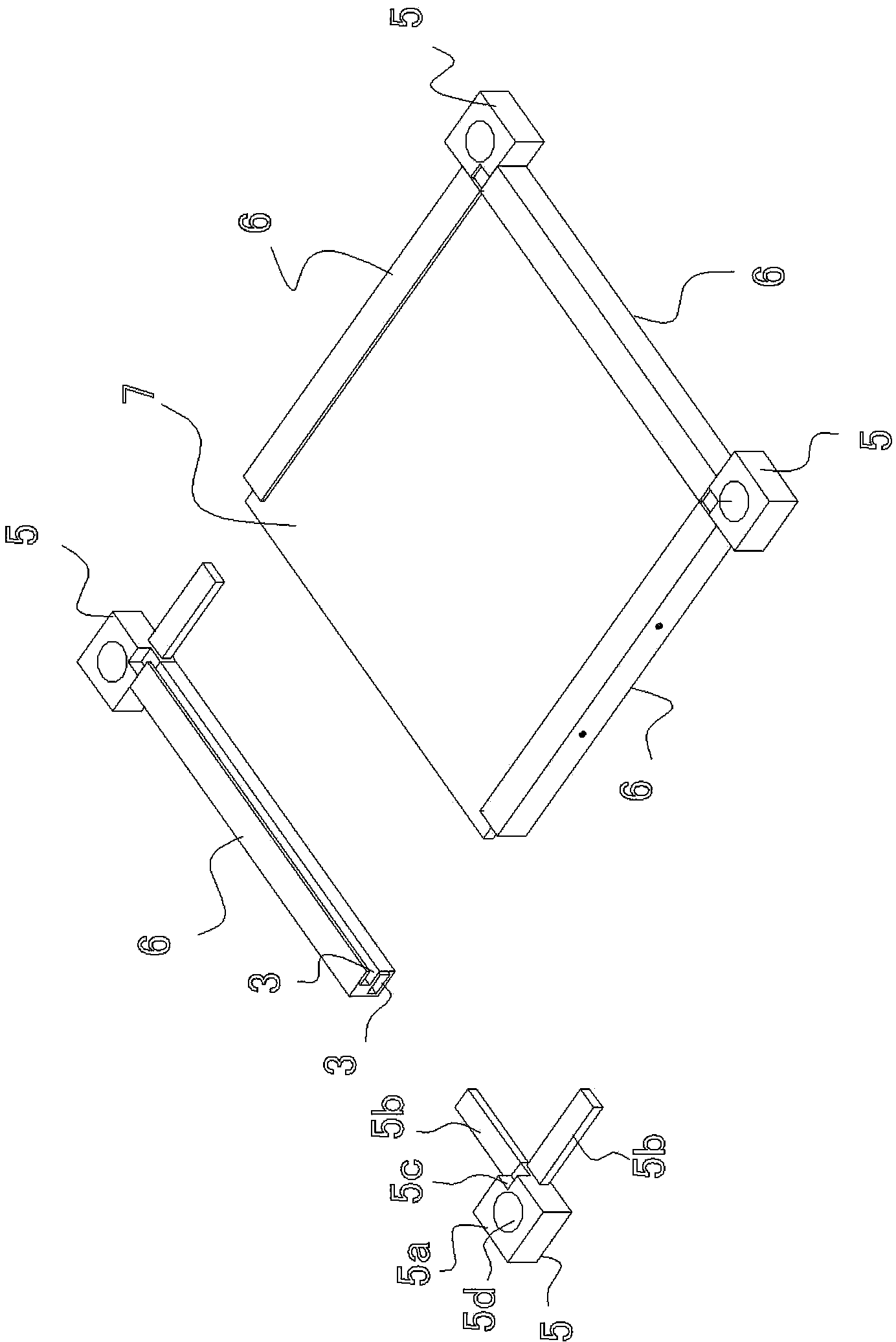
[0018] Embodiment one: if figure 1 , 2 , 3, the present embodiment includes four columns 1 and two panels 2, and its special feature is that the columns 1 include cabinet feet 3 and sub-columns 4 connected to the cabinet feet 3, such as figure 2 As shown, the upper end of the cabinet foot 3 is provided with a screw hole 3a, and the sub-column 4 includes a column body 4a, a screw hole 4b arranged at one end of the column body 4a, and a stud 4c arranged at the other end of the column body 4a, such as image 3 As shown, the panel 2 includes four connectors 5 made of plastic, an aluminum profile 6 connected between the four connectors 5, and a plate 7 made of tempered glass. The connector 5 includes a connector 5a whose upper and lower ends are parallel to each other. , the connecting columns 5b arranged at the side of the connecting body 5a at an angle of 90 degrees to each other, and a falling step 5c on the connecting body 5a between the two connecting columns 5b, the aluminu...

Embodiment 2

[0021] Embodiment 2: as Figure 4 As shown, this embodiment is based on Embodiment 1. The upper end of the cabinet foot 3 is provided with a stud 3b, and the through hole 5d on the connector 5 on one panel 2 is set on the stud of the cabinet foot 3. 3b, the screw hole 4b of the sub-column 4 is screwed on the stud 3b of the cabinet foot 3, and the through hole 5d on the connector 5 of the other panel 2 is set on the stud 4c of the sub-column 4 and fixed by a nut 13 On the stud 4c of the sub-column 4, the panel 2 has n pieces (the embodiment is 3 pieces), n>2, the sub-column 4 has n-1 pieces (the embodiment is 2 pieces), and the nth panel 2 is arranged on The n-2th sub-column 4 and the n-1 sub-column 4 are fixed through the studs 4c and screw holes 4b of the two sub-columns.

Embodiment 3

[0022] Embodiment 3: as Figure 5 As shown, the present embodiment is on the basis of Embodiment 1, is provided with two middle columns 14, the middle columns 14 include the middle cabinet foot 15, the middle sub-column 16 connected on the middle cabinet foot 15, the upper end of the middle cabinet foot 15 Screw holes are provided, and the structure of the middle sub-column 16 is the same as that of the sub-column 4, and also includes a column body, a screw hole arranged at one end of the column body, and a stud column arranged at the other end of the middle column body, such as Image 6 As shown, intermediate connectors 17 are provided on both sides of the middle of the first and second panels 2 corresponding to the bottom end and top end of the intermediate column 16, and the intermediate connectors 17 include intermediate connectors 17a whose upper and lower end surfaces are parallel to each other, and are arranged in a straight line. On the intermediate connecting column 1...


PUM


Abstract

The invention provides a cabinet convenient to assemble. The cabinet comprises four stand columns and two panels and is characterized in that each stand column comprises a cabinet leg and a sub-stand-column, each sub-stand-column comprises a stand column body, a screw hole and a stud, each panel comprises four connecting pieces, aluminum sections and plates, the aluminum sections and the plates are connected among the four connecting pieces, the four connecting pieces and the aluminum sections are connected to form a frame-like object, the plates are embedded into embedding grooves of the frame-like objects, the corners of the plates are supported on steps of the connecting pieces, the middle portions of the connecting pieces are provided with penetration holes, the studs of the sub-stand-columns penetrate through the penetration holes in the connecting pieces of one panel and are screwed into the screw holes of the cabinet legs, and the other panel is arranged at the screw hole ends of the sub-stand-columns and fixed to the sub-stand-columns through the penetrating bolts. Compared with the prior art, the cabinet has the advantages of being convenient to disassemble and assemble and transport; moreover, the firmness of the structure of the cabinet after being assembled can not be influenced even if the cabinet is disassembled and assembled many times.

Description

Technical field: [0001] The present invention relates to a kind of furniture. Background technique: [0002] Existing cabinets that are easy to assemble are generally formed by connecting the main side panels and main panels through hooks and buckles inserted into the panels. Since they rely on the main side panels and main panels as the auxiliary structure of the cabinet, they must be relatively thick to meet the requirements. Requirements, when assembling, you first need to stand up the main side panel. Without support, it is not easy to make the main side panel stand up stably. In addition, it is determined by the material of the side panel and the panel. It is not suitable to disassemble after assembly, because as the number of disassembly and assembly increases, the connection holes of the side panels and panels will continue to expand, resulting in a significant decrease in the firmness after reassembly. Invention content: [0003] The object of the present inventio...

Claims


Application Information

Patent Timeline
IPC IPC(8): A47B47/00
Inventor 端木乐善胡波
Owner 胡波
Why Eureka
Try Eureka