
Testing method and testing platform for light spot patterns of solar light condenser

A technology of a solar concentrator and a test method, applied in the field of solar photovoltaic power generation, can solve the problems of spot shape error, affecting system efficiency, etc., and achieve the effects of high test efficiency, high spot size accuracy, and automation of the test process.

Inactive Publication Date: 2014-05-28
HUAZHONG UNIV OF SCI & TECH
View PDF6 Cites 9 Cited by
  • Summary
  • Abstract
  • Description
  • Claims
  • Application Information

AI Technical Summary

Problems solved by technology

[0005] For reflective concentrated power generation, the shape of the light spot incident on the receiver plays a key role in optimizing the system efficiency. For a given receiver, the optimization degree of the system depends on the best receiving position and the most uniform light spot Distribution, these factors are determined by modifying the tracking parameters and the curvature of the reflective surface. However, in actual manufacturing, there are often some problems that affect system efficiency:
[0008] In addition, the traditional manufacturing of high-reflectivity surfaces mainly includes surface anodic oxidation electroplating aluminum film methods, surface electroplating methods, and surface-mounted high-reflectivity acrylic mirror methods. Due to manufacturing process factors, these methods are used to mass-produce high-reflection condenser mirrors. There are also some manufacturing defects on the high-frequency surface, and these defects will also bring some errors to the shape of the spot. How to consider the impact of these defects, it is necessary to analyze the impact of the entire condenser on the shape of the spot.

Method used


Image

  • Testing method and testing platform for light spot patterns of solar light condenser
  • Testing method and testing platform for light spot patterns of solar light condenser
  • Testing method and testing platform for light spot patterns of solar light condenser

Examples


Embodiment Construction

[0048]In order to make the object, technical solution and advantages of the present invention clearer, the present invention will be further described in detail below in conjunction with the accompanying drawings and embodiments. It should be understood that the specific embodiments described here are only used to explain the present invention, not to limit the present invention. In addition, the technical features involved in the various embodiments of the present invention described below can be combined with each other as long as they do not constitute a conflict with each other.

[0049] Traditional solar concentrators often have various shapes, figure 1 Several common solar concentrators are given, among which (1) is a rectangular concentrator with a certain parabola, (2) is a trough concentrator, (3) is a parabolic concentrator, various concentrators The characteristics of different devices are different, but the general idea is to use a relatively large concentrating s...


PUM

PropertyMeasurementUnit
Wavelengthaaaaaaaaaa

Abstract

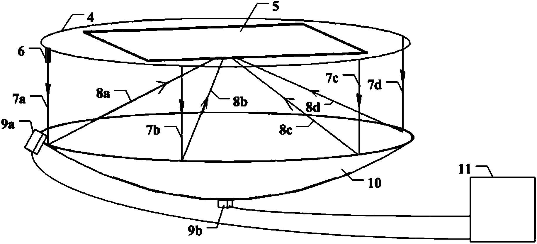
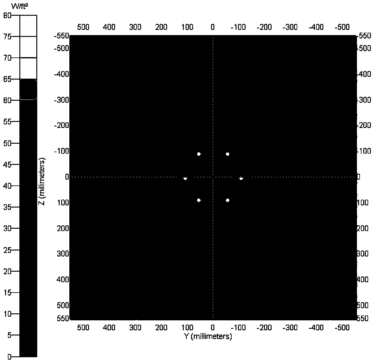
The invention provides a testing method for light spot patterns of a solar light condenser. The testing method comprises the following steps: firstly, generating light rays which are vertically incident on a solar light condensing lens by utilizing simulation point light sources; then acquiring geometric information about the position and the shape of condensed light on a receiver by utilizing an image detecting technique, and reconstructing and recognizing on a computer; then moving the simulation point light sources fixed on a guide rail along the outer diameter of the solar light condensing lens in parallel by utilizing the electric guide rail with a servo stepping motor, reconstructing and storing the position and the shape of the condensed light after each moving, and automatically analyzing the shape and the position of a light spot on the receiver by testing software after the simulation point light sources move for a cycle, thereby obtaining the accurate light receiving patterns. The invention also provides a testing platform for light spot patterns of the solar light condenser. The testing method and the testing platform provided by the invention can directly measure the actual light spot size after light condensation, and moreover, the obtained light spot is high in size accuracy; additionally, the testing process is automatic, so that the testing efficiency is high.

Description

technical field [0001] The invention belongs to the technical field of solar photovoltaic power generation, and in particular relates to a test method and a test platform for the spot shape of a solar concentrating mirror. Background technique [0002] Concentrating solar energy is to gather the solar energy with thin energy density into a beam with high energy density through the principle of light focusing, so that the solar energy can be used more widely and more effectively. [0003] Generally speaking, solar energy concentrating methods are divided into reflective concentrating and refracting concentrating. The so-called reflective concentrating means that the incident sunlight passes through the concentrator and converges on the receiver according to the law of light reflection; while the so-called refracting concentrating is It uses the principle of refraction of incident light through transparent materials to gather sunlight. [0004] Photovoltaic power generation t...

Claims


Application Information

Patent Timeline
IPC IPC(8): G01M11/02G01B11/24
Inventor 官成钢刘文王双保吴展翔李树辉温晨龙严兴隆
Owner HUAZHONG UNIV OF SCI & TECH
Learn More