Self-propelled typed stack silage reclaimer

A reclaimer and self-propelled technology, applied in the field of silage stacking and reclaiming machines, can solve the problems of slow reclaiming, short conveying distance of the blower, slow reclaiming of reclaimers, etc., and achieve a simple and fast conveying process, Save operating time, and the effect of high reclaiming height

Inactive Publication Date: 2014-05-28
ANHUI DAMING FARMING MACHINERY
View PDF6 Cites 1 Cited by
  • Summary
  • Abstract
  • Description
  • Claims
  • Application Information

AI Technical Summary

Problems solved by technology

At present, there are mainly two types of silage reclaimers. One is a silage cutting loader suspended on a tractor. It is blown into the feeding cart through the blower, and it is generally a large-scale tractor with a suspension. It is mainly suitable for a place where the work site is relatively spacious and easy to turn. It is not suitable for flat but narrow places such as silage piles and ground silage pits; the other is the self-propelled silage reclaimer. The existing self-propelled silage reclaimers all use a special chassis with its own engine power. Feed is taken out through the cutting drum set at the front end of the lifting arm, and the feed collected by the collecting hopper is transported to the feeding cart through the conveying device. The structure is complex and the size is large, so it is not suitable for flat but narrow sites such as silage piles and ground silage pits. places, and these two types of reclaimers are slow in retrieving materials. Generally, it takes about 30 minutes to reclaim a car full of about 1.5 tons of silage. The reclaiming is relatively slow and the work efficiency is low.

Method used


Image

  • Self-propelled typed stack silage reclaimer

Examples


Embodiment Construction

[0022] The technical solution and structure of the present invention will be described below in conjunction with the accompanying drawings, so as to facilitate the understanding of those skilled in the art.

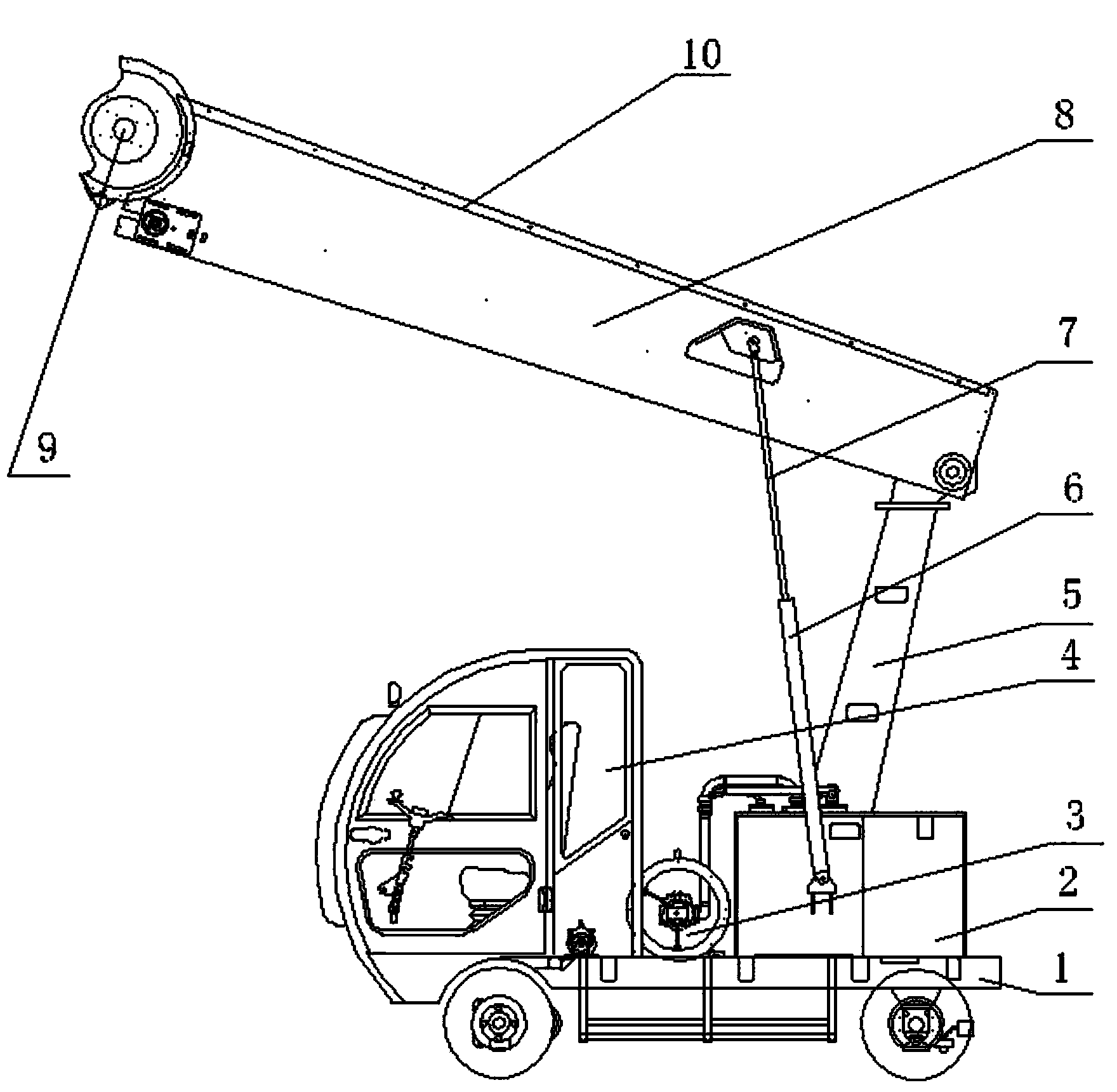
[0023] Such as figure 1 As shown, a self-propelled silage stacker and reclaimer includes an automobile chassis 1 driven by a motor, a control room 4 is arranged on the left side of the front end of the upper part of the chassis 1, and a hydraulic oil tank is arranged on the chassis 1 at the rear of the control room 4. 2. The chassis 1 on the right side of the hydraulic oil tank 2 is provided with a vertical boom 5, the top of the boom 5 is connected with a retrieving arm 8 extending to the front of the chassis 1, and the retrieving arm 8 is provided with a The retrieving drum 9 is provided with a retrieving blade, the retrieving arm 8 is provided with a conveying mechanism 10, the hydraulic oil tank 2 is connected with a hydraulic cylinder 6, the hydraulic push rod 7 of t...


PUM


Abstract

The invention relates to a self-propelled typed stack silage reclaimer capable of integrating material taking and conveying function. The self-propelled typed stack silage reclaimer comprises an automotive chassis driven by a motor, a control room is arranged on left side of the front end of the upper portion of the chassis, a hydraulic oil tank is arranged on the chassis of the back portion of the control room, a vertical cantilever crane is arranged on the chassis of the right side surface of the hydraulic oil tank, a material taking arm protruding to the front portion of the chassis is connected with the top of the cantilever crane, a material taking roller is arranged at a position of the material taking arm far away from the cantilever crane, a material taking blade is arranged on the material taking roller, a conveying mechanism is arranged inside the material taking arm, a hydraulic cylinder is connected with the hydraulic oil tank, and a hydraulic pushing rod of the hydraulic cylinder is connected with the material taking arm. The self-propelled typed stack silage reclaimer is in pure electricity and hydraulic control to connect the charging mechanism with the conveying device, fodder cut by the material taking roller can be rapidly and timely conveyed to an aggregating conveying car at the back from the conveying mechanism inside the material taking arm, and material taking speed is high.

Description

technical field [0001] The invention belongs to silage retrieving equipment, and more specifically relates to a self-propelled, fast retrieving silage stacking and reclaiming machine integrated with retrieving and conveying connections. Background technique [0002] Because the silage is stored by compacted anaerobic fermentation, the material pile is high and dense, which brings great difficulties to feeding and feeding. Therefore, a special silage reclaimer is required to cut and reclaim the material, and then transport it to the feeding trailer. on, and then transported to the breeding grounds for feeding. At present, there are mainly two types of silage reclaimers. One is a silage cutting loader suspended on a tractor. It is blown into the feeding cart through the blower, and it is generally a large-scale tractor with a suspension. It is mainly suitable for a place where the work site is relatively spacious and easy to turn. It is not suitable for flat but narrow place...

Claims


Application Information

Patent Timeline
Patent Type & Authority Applications(China)
IPC IPC(8): B65G65/02B65G65/28
Inventor 赵风雷赵勇杨帆张东东张上元
Owner ANHUI DAMING FARMING MACHINERY
Why Eureka
Try Eureka