Laser cutting equipment for cutting pipes

A laser cutting and pipe cutting technology, which is applied in laser welding equipment, welding/cutting auxiliary equipment, welding equipment, etc., can solve the problems of large pipe deformation, affecting product quality, and low cutting efficiency, so as to reduce clamping deformation and cut Good quality, good neutral effect

Active Publication Date: 2015-08-26
JIANGSU HEFENG MECHANICAL MAKING
View PDF7 Cites 1 Cited by
  • Summary
  • Abstract
  • Description
  • Claims
  • Application Information

AI Technical Summary

Problems solved by technology

[0002] Ordinary laser cutting equipment for cutting pipes includes a manual clamping mechanism and a laser cutting mechanism arranged adjacently. After the cutting is completed, the clamping mechanism needs to be manually released to feed and clamp before cutting again. The cutting efficiency Low
Moreover, due to the large length of the pipe, single-end clamping is easy to cause large deformation of the pipe, which affects the quality of the cut product

Method used


Image

  • Laser cutting equipment for cutting pipes
  • Laser cutting equipment for cutting pipes
  • Laser cutting equipment for cutting pipes

Examples


Embodiment Construction

[0024] The specific embodiments of the present invention will be described in detail below with reference to the drawings.

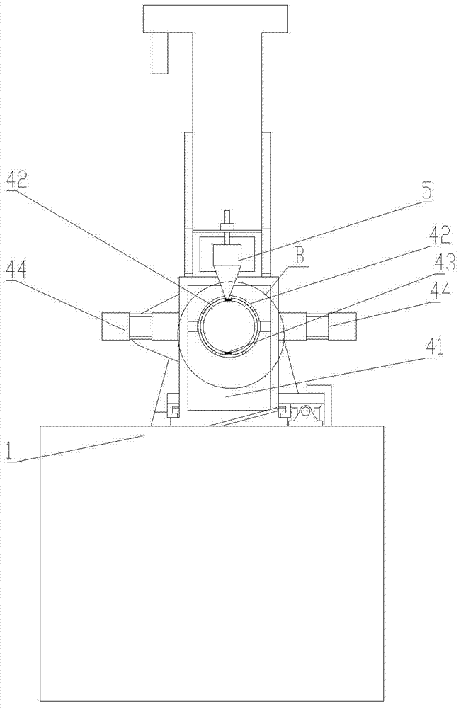
[0025] Such as Figure 1-4 As shown, a laser cutting device for cutting pipes includes a base 1 on which a guide mechanism 2, a main clamping mechanism 3, an auxiliary clamping mechanism 4, and a laser cutting mechanism 5 are sequentially arranged.

[0026] The guide mechanism 2 includes a mounting seat 21 arranged on the base 1. A circular through hole is provided in the mounting seat 21 along the feeding direction. The circular through hole is detachably provided with an inner diameter matching the diameter of the pipe to be cut. The cylinder sleeve 22 is provided with at least three grooves along the pipe conveying direction in the circumferential direction of the inner surface of the cylinder sleeve 22, and a number of balls 23 are arranged in the grooves.

[0027] The main clamping mechanism 3 includes a lead screw 31 movably arranged on the base 1, a main...


PUM


Abstract

The invention discloses laser cutting equipment used for cutting pipes, which has the advantages that automatic feeding is realized, the clamping is steady and the cutting quality is good. The laser cutting equipment comprises a base, wherein a guide mechanism, a main clamping mechanism, an auxiliary clamping mechanism and a laser cutting mechanism are arranged on the base in sequence; the main clamping mechanism comprises a screw rod which is movably arranged on the base; a main motor which is used for driving the screw rod is arranged on the base; a sliding seat is sleeved on the screw rod; a sliding rail is arranged on the base; the bottom of the sliding seat is movably clamped on the sliding rail; a feeding hole is formed in the sliding seat; a barrel-shaped clamping component is embedded in the feeding hole; a plurality of flexible grooves are arranged in the periphery of the discharge end of the clamping component; a plurality of grooves are arranged in the periphery of the external surface of the part, stretching out of the sliding seat, of the discharge side of the clamping component; the depths of the grooves are gradually reduced in the feeding direction; a movable sleeve is sleeved on one section, provided with the grooves, of the clamping component; a plurality of grooves which are matched with the grooves of the external surface of the clamping component and are formed in the feeding direction are formed in the periphery of the inner surface of the movable sleeve; balls are arranged between the grooves of the movable sleeve and the grooves of the clamping component; a main air cylinder used for driving the movable sleeve to move is arranged on the sliding seat.

Description

Technical field [0001] The invention relates to a laser cutting equipment for cutting pipes. Background technique [0002] Common laser cutting equipment for cutting pipes includes a manual clamping mechanism and a laser cutting mechanism arranged adjacently. After this cutting is completed, the clamping mechanism needs to be manually released and then the material is fed and clamped before it can be cut again. The cutting efficiency low. Moreover, due to the large length of the pipe, the single-end clamping is likely to cause large deformation of the pipe, which affects the quality of the product after cutting. Summary of the invention [0003] The technical problem to be solved by the present invention is to provide a laser cutting equipment for cutting pipes with automatic feeding, stable clamping and good cutting quality. [0004] In order to solve the above technical problems, the technical solution adopted by the present invention is: a laser cutting device for cutting pipes...

Claims


Application Information

Patent Timeline
Patent Type & Authority Patents(China)
IPC IPC(8): B23K26/38B23K26/70B23K37/053
CPCB23K26/38B23K26/702B23K37/0533B23K2101/06
Inventor 林洪才张建李钦奉陶志高唐文献苏世杰林永才杭世峰
Owner JIANGSU HEFENG MECHANICAL MAKING
Why Eureka
Try Eureka