


Quick Research
Generate reliable direction feasibility study reports for your R&D in just a few steps.

Technical Q&A
Discover and master advanced knowledge NOW. Basics, ideas, possibilities, all at once.

Find Solutions
As an expert in R&D theories, this can generate solutions to your technical problems instantly.

Evaluate Feasibility
Analyze your overall solution with one click, know your potential R&D risks in advance.

Monitor Landscape
Get weekly tech updates, stay abreast of the latest tech innovations and key insights.
DC (Direct Current)-AC (Alternating Current) transfer circuit and control method thereof
A technology for converting circuits and DC power supplies, which is applied in the direction of converting AC power input to DC power output, photovoltaic power generation, and electrical components. The effect of increasing frequency
- Summary
- Abstract
- Description
- Claims
- Application Information
AI Technical Summary
Problems solved by technology
Method used
Image


Examples
Embodiment 1
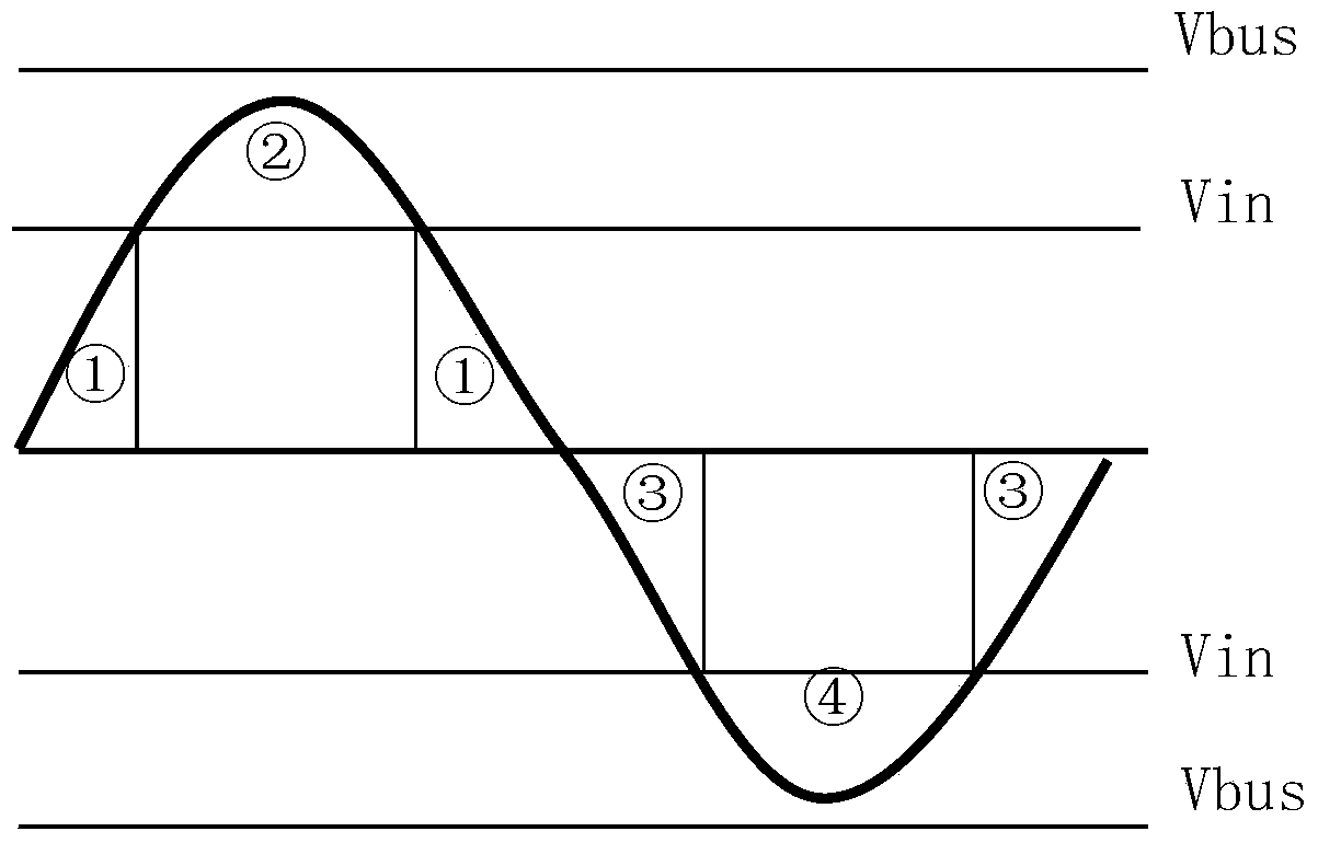
[0023] like figure 1 The shown DC-AC conversion circuit includes boost inductor L1, boost switch tube Q7, rectifier diode D8, first to fourth capacitors C1, C2, C3, C4, inverter bridge freewheeling diode D2, inverter bridge, The first to the second output filter inductors L2, L3.
[0024] In the DC-AC conversion circuit, one end of the boost inductor L1 is connected to the positive input end of the DC power supply, and the other end is connected to the drain of the boost switch tube Q7 and the anode of the rectifier diode D8; the boost The source of the switch tube Q7 is connected to the negative input terminal of the DC power supply DC input; the cathode of the rectifier diode D8 is connected to the positive pole of the second capacitor C2 through the positive bus bus; the negative pole of the second capacitor C2 is connected to the DC power supply The positive input terminal of the fourth capacitor C4 is connected in parallel with the first capacitor C1, and the positive po...
Embodiment 2
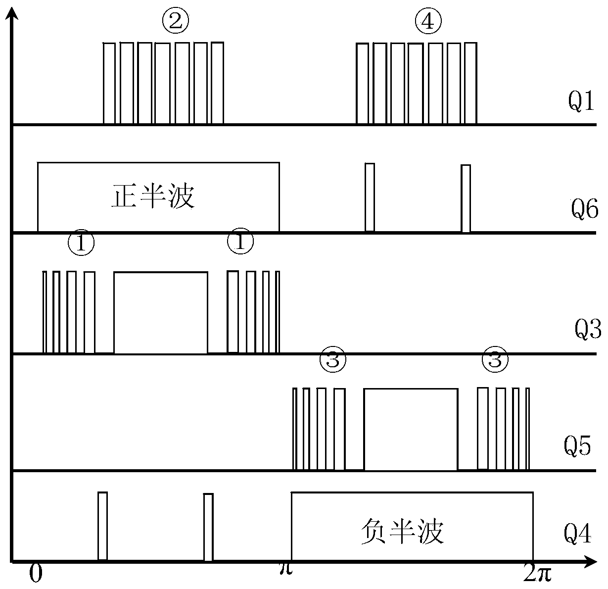
[0032] like Figure 4 As shown, it is another embodiment of the present invention, the difference is that the switch tube Q2 in the circuit replaces the D2 of the first embodiment. When the inverter output waveform is in the aforementioned region ①③, the switching tube Q2 can be always turned on by applying a high level, which is equivalent to the synchronous rectification in the first embodiment. In the foregoing ② and ④ region, when freewheeling is required, the switching tube Q2 can be turned on by applying a PWM driving signal complementary to the switching tube Q1. The other parts are not different from the embodiment, so they will not be described again.
[0033] The switching tubes in the present invention can be various high-speed bidirectional switches controlled by driving signals, such as MOSFETs or IGBTs, and are not limited to the power semiconductor switches shown in the figure.
PUM
 Abstract
Description
Claims
Application Information
 - R&D Engineer
- R&D Manager
- IP Professional
- Industry Leading Data Capabilities
- Powerful AI technology
- Patent DNA Extraction
Browse by: Latest US Patents, China's latest patents, Technical Efficacy Thesaurus, Application Domain, Technology Topic, Popular Technical Reports.
© 2024 PatSnap. All rights reserved.Legal|Privacy policy|Modern Slavery Act Transparency Statement|Sitemap|About US| Contact US: help@patsnap.com