Simulation device and method

A simulation device and process simulation technology, applied in the simulation device and field, can solve problems such as the influence of mold clamping performance, and achieve the effect of rapid adjustment

Active Publication Date: 2017-04-12
ENGEL AUSTRIA
View PDF2 Cites 0 Cited by
  • Summary
  • Abstract
  • Description
  • Claims
  • Application Information

AI Technical Summary

Problems solved by technology

However, since accurate injection properties and mold clamping properties in injection molding have a great influence on the final product of the injection molding process, the accuracy of the process simulation is open to improvement

Method used


Image

  • Simulation device and method
  • Simulation device and method

Examples


Embodiment Construction

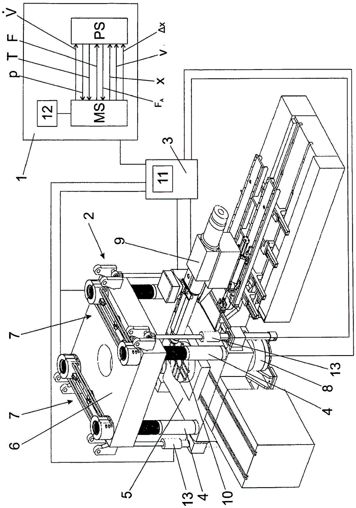
[0026] figure 1 An injection molding machine 2 is shown and its regulating or control unit 3 and simulation device 1 are schematically shown. A vertical clamping unit with vertical bars 4 , a fixed clamping plate 5 and a movable clamping plate 6 is shown here by way of example. Of course, the invention can also be used with any other type of clamping unit. The regulating or control unit 3 is usually connected to all important elements of the injection molding machine 2 . The connections to the rapid stroke cylinder 13 , the locking mechanism 7 , the pressure mechanism 8 and the injection unit 9 are shown here by way of example.

[0027] The clamping unit is shown here in the open state, so that the mold halves of the injection mold 10 are visible.

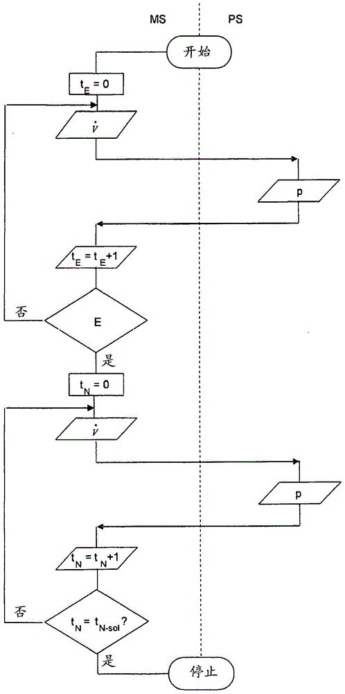
[0028] The machine simulator MS and the process simulator PS are operated in the simulation device 1 , wherein in each simulation step the pressure p calculated by the process simulator PS is transmitted to the machine simulator...


PUM


Abstract

The method involves calculating volumetric flow (V-) parameter of a physical model in a machine simulation unit (MS) for simulating an injection molding machine (2). The to-be-processed molding material is simulated for calculating the pressure parameter (p) of to-be-processed molding material in a process simulation unit (PS). The parameter calculated in the process simulation unit is notified through an interface (12) for entering the parameters calculated in the machine simulation unit corresponding to an input mask (11) of the injection molding machine. Independent claims are included for the following: (1) simulating device for injection molding process of injection molding machine; and (2) injection molding machine.

Description

technical field [0001] The invention relates to a method for simulating the injection molding process, and also to a simulation device for simulating the injection molding process and an injection molding machine with the simulation device. Background technique [0002] It is known to simulate injection molding machines, in which the machine movements are calculated, inter alia, on the basis of defined cyclic processes and on the basis of the behavior of the drive components. Such software is primarily used for training the operators of injection molding machines and also for testing the machine software. [0003] Also known are process simulations, in which the injection mold is simulated as a three-dimensional model and the molding process is simulated starting from the injection of the melt, through the pressure-holding phase and cooling, until the ejection of the finished part. For a given cavity geometry, pressure and temperature calculations can be made in this proces...

Claims


Application Information

Patent Timeline
Patent Type & Authority Patents(China)
IPC IPC(8): B29C45/00B29C45/76
CPCB29C45/766G05B17/02G06F30/20B29C45/7693B29C2045/7606G09B19/24G05B19/41885G05B2219/45244Y02P90/02
Inventor J·吉绍夫
Owner ENGEL AUSTRIA
Why Eureka
Try Eureka