
Fluid storage muffler

A technology of silencer and liquid storage, applied in the direction of non-removable pipe connection, pipe/pipe joint/pipe fitting, through components, etc., can solve the problems of difficult welding quality assurance, increased process difficulty, and large thermal influence of copper pipes. , to achieve the effect of improving welding manufacturability, avoiding weld corrosion and ensuring welding reliability.

Active Publication Date: 2014-05-14
XINCHANG COUNTY SITONG ELECTRICAL CO LTD
View PDF6 Cites 14 Cited by
  • Summary
  • Abstract
  • Description
  • Claims
  • Application Information

AI Technical Summary

Problems solved by technology

Although such a structure saves part of the cost, it is necessary to weld the copper air inlet / outlet pipe to the stainless steel cylinder during the manufacturing process. Because the welding characteristics of the copper material and the stainless steel material are very different, such as a simple The implementation of welding increases the difficulty of the process and the quality of welding is not easy to guarantee
In addition, the welding temperature of stainless steel materials is relatively high, and the thermal influence on the copper pipe after welding is increased, and the material is also soft, which is easy to cause bruises in the subsequent manufacturing assembly and twists and turns. At the same time, after welding in such an environment, The grain size of the copper pipe material is coarse. Since the muffler and the liquid receiver are generally installed next to the compressor, long-term work in a vibrating environment produces stress changes, and the cracking of the copper pipe causes the system to fail.

Method used


Image

  • Fluid storage muffler
  • Fluid storage muffler
  • Fluid storage muffler

Examples


Embodiment Construction

[0028] The technology of the present invention will be described below in conjunction with specific embodiments.

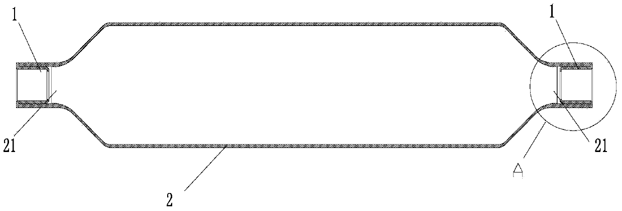
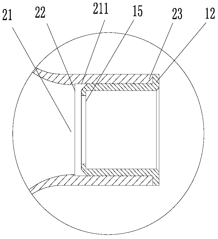
[0029] figure 1 Structural schematic diagram of the preferred liquid storage muffler provided by the present invention; figure 2 is an enlarged schematic diagram of the end position of the receiver silencer, image 3 Schematic diagram of the preferred connection sleeve.

[0030] Such as figure 1 , figure 2 and image 3 shown. The liquid storage muffler provided by the present invention adopts stainless steel pipe material to form the main body 2 through spinning, and the connection ports 21 for fluid inflow and fluid outflow are formed at both ends of the main body 2 through necking, and the inner wall surface of the connection port 21 211 is provided with a stepped surface 22 .

[0031] The connecting sleeve 1 made of copper pipe includes a generally cylindrical body part 11, a raised end part 12 is formed by flanging outward at one end of the body par...


PUM


Abstract

The invention relates to a fluid storage muffler, and belongs to the technical field of refrigeration. The fluid storage muffler comprises a body (2) made of stainless steel, and connection ports (21) allowing fluid to flow in and flow out are formed in the body (2). The fluid storage muffler is characterized in that a connecting sleeve (1) made of a copper material is welded and fixed in at least one of the connection ports (21), each connecting sleeve (1) comprises a barrel portion (11) and a protruding end portion (12) formed by flanging outwards from the barrel portion (11), an outer wall (111) of each barrel portion (11) is matched with an inner wall (211) of the corresponding connection port (21), and each protruding end portion (12) is matched with an end portion (23) of the corresponding connection port (21). The fluid storage muffler is high in working reliability, products of manufacturers can realize universality, cost is lowered on the premise that welding reliability of the products is guaranteed, and environmental pollution in the manufacturing process and copper pipe deformation in the transportation process are reduced.

Description

technical field [0001] The invention belongs to the technical field of refrigeration, and mainly relates to a liquid storage muffler used for pipeline control in an air conditioning system. Background technique [0002] The liquid receiver or muffler (liquid storage muffler) is a basic component in the refrigeration system. It can be used as a liquid receiver in the system to store excess refrigerant in the system; it can also be used as a muffler to allow air to pass through and Equipment that can effectively reduce noise. [0003] The commonly used liquid storage muffler includes a cylinder with a larger diameter and an inlet pipe and an outlet pipe with a smaller diameter welded to both ends of the cylinder. The cylinder body, inlet pipe and outlet pipe of the traditional liquid storage muffler are all made of copper pipes. The high price of copper materials makes the cost of the liquid storage silencer relatively high, and the liquid storage silencer using copper materi...

Claims


Application Information

Patent Timeline
IPC IPC(8): F16L55/033
CPCF16L13/013F16L13/02F16L13/0227F16L55/033
Inventor 不公告发明人
Owner XINCHANG COUNTY SITONG ELECTRICAL CO LTD
Learn More