
An automatic floating lubrication type high-lift multi-stage pump

A multi-stage pump and high-lift technology, applied in radial flow pumps, pumps, pump components, etc., can solve problems such as impeller stuck, affecting product service life, processing errors, etc., to avoid damage, prolong service life, improve The effect of service life

Inactive Publication Date: 2016-03-30
HEBEI QIANDA SPECIAL PUMP IND
View PDF5 Cites 0 Cited by
  • Summary
  • Abstract
  • Description
  • Claims
  • Application Information

AI Technical Summary

Problems solved by technology

This structure has the following defects: (1) Since the impeller is axially fixed and compacted step by step on the pump shaft, the single-stage impeller does not have the ability to adjust up and down by itself, and the pressure difference generated by the front and rear cover plates of the impeller during operation, Axial force is formed, transmitted to the pump shaft, and then transmitted to the motor bearing step by step, causing the motor bearing load to increase and be easily damaged, affecting the service life of the product. The solution is generally to eliminate it by installing an axial force decomposition device or a balance device axial force
(2) Due to the error in the height of the impeller during processing (generally 0 to 0.15mm), after multi-stage assembly (more than 25 stages, that is, accumulatively assembling 25 impellers), the cumulative processing error generated will offset the overall design of the pump The amount of movement (generally 3.5 mm), the final effective movement amount is 0, or even a negative number, causing the impeller to be stuck and unable to operate, especially for high-lift (above 500 meters) multi-stage pumps; (3), because the impeller is working The axial force generated at the time causes the impeller to move up and down, and the effective movement amount of the multi-stage pump after assembly is reduced due to the processing error of the impeller height, so that the impeller of the multi-stage pump is easy to cause friction and damage to the pump casing. Affect product life

Method used


Image

  • An automatic floating lubrication type high-lift multi-stage pump
  • An automatic floating lubrication type high-lift multi-stage pump
  • An automatic floating lubrication type high-lift multi-stage pump

Examples


Embodiment Construction

[0030] The present invention will be further described in detail below in conjunction with the accompanying drawings.

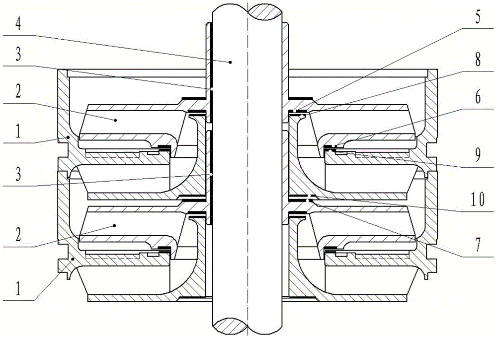
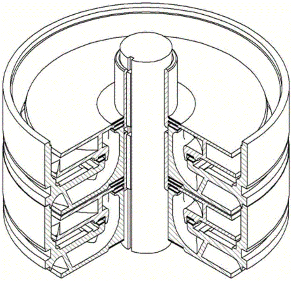
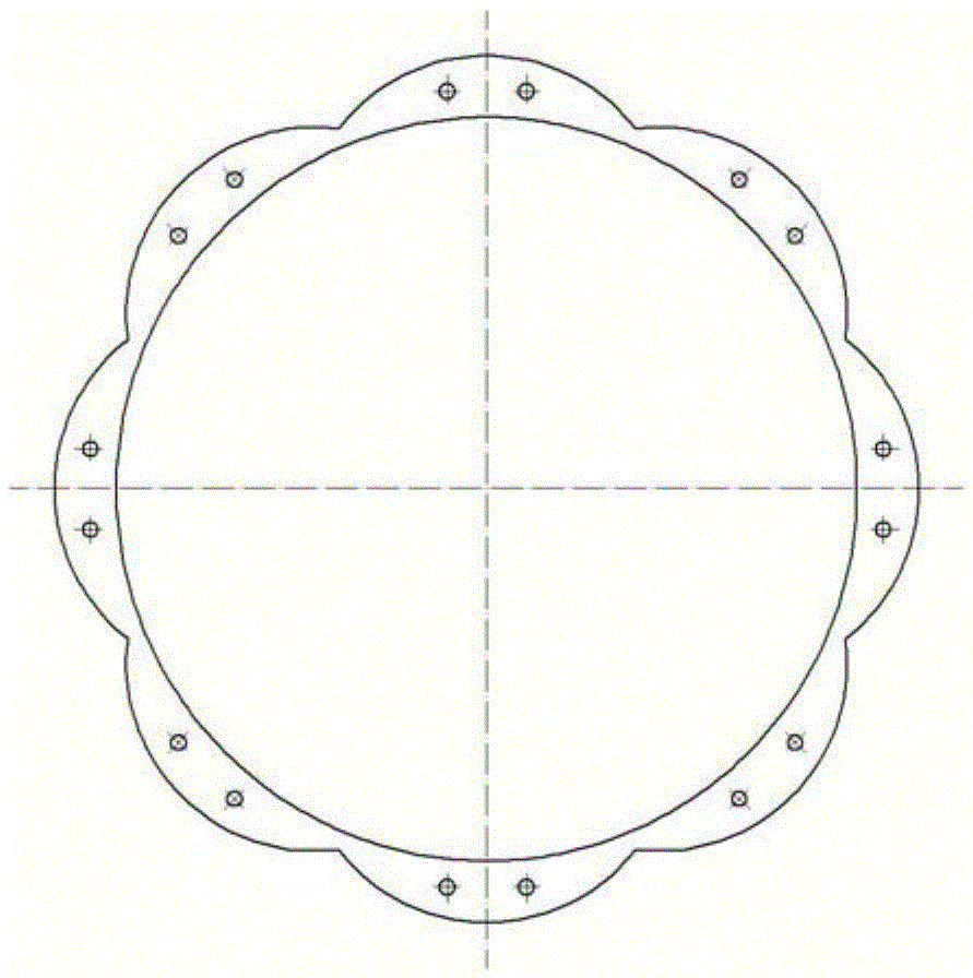
[0031] see Figure 1 to Figure 8 .

[0032] An automatic floating lubrication type high-lift multi-stage pump, which is composed of multi-stage pumps, and each stage pump includes a pump casing 1, a pump shaft 4, and an impeller 2 mounted on the pump shaft through a key 3, and the impeller 2 is located on the pump shaft. Inside the pump casing 1;

[0033] The impeller is provided with a first impeller friction plate 5, a second impeller friction plate 6 and a third impeller friction plate 7, the shape of the three impeller friction plates is a petal-shaped ring edge, and the petal-shaped ring There are several micro-holes on the top, the first impeller friction plate 5 is located at the lower end of the impeller upper cover plate along the pump shaft 4, and the second impeller friction plate 6 is located at the lower end of the impeller lower cover plate, a...


PUM


Abstract

The invention belongs to the technical field of water pumps, and relates to an automatic floating and lubricating type high-lift multistage pump. The automatic floating and lubricating type high-lift multistage pump is composed of a plurality of stages of pumps. The pump at each stage comprises a pump shell, a pump shaft and impellers installed on the pump shaft through keys, wherein the possible contact positions between an upper end cover and a lower end cover of the impellers on one side and the pump shell on the other side are provided with inlay annular petal-shaped impeller friction sheets provided with micro-holes or impeller friction sheets provided with annular water grooves or strip-shaped water grooves, the corresponding pump shell positions are provided with annular pump shell abrasion-resisting sheets in an inlay mode so that a set of opposite abrasion pairs can be formed, the effect of a local microcirculation pump can be produced when a water pump works, liquid is brought into the middle portions of the opposite abrasion pairs to form a water film so that the opposite abrasion pairs can be protected, and therefore the friction coefficients can be reduced, the service life of the opposite abrasion pairs can be greatly prolonged, the damage, caused by friction, of the impellers and the pump shell is avoided, and the service life of the water pump is prolonged. The impellers can slightly float in pump cavities, the axial force of the impellers can be automatically balanced, eccentric abrasion cannot happen, operation is carried out stably and reliably, the working performance is superior, the structure is simple, and cost is low.

Description

technical field [0001] The invention belongs to the technical field of water pumps and relates to an automatic floating lubrication type high-lift multistage pump. Background technique [0002] Existing multistage pumps are composed of impellers, pump casings, pump shafts and other parts, and then assembled with motors, water inlet joints, and check valves. The structure is fixed inside the pump casing with pump shafts. When working, the pump shaft transmits the power of the motor to the impeller, and the impeller works to transmit the liquid through the pump casing to the impeller of the next stage, which is lifted step by step, and finally guides the liquid to the check valve through the last stage of the pump casing, and then Discharged by check valve. This structure has the following defects: (1) Since the impeller is axially fixed and compacted step by step on the pump shaft, the single-stage impeller does not have the ability to adjust up and down by itself, and the p...

Claims


Application Information

Patent Timeline
Patent Type & Authority Patents(China)
IPC IPC(8): F04D1/06F04D29/22F04D29/02
Inventor 姚清辉
Owner HEBEI QIANDA SPECIAL PUMP IND
Learn More