
High lift floating impeller well submersible pump

A submersible electric pump and floating technology, which is applied to non-variable capacity pumps, components of pumping devices for elastic fluids, pumps, etc. Serious problems, to achieve the effect of improving the installation process, reducing product parts, and eliminating the stuck pump body

Active Publication Date: 2016-03-30
陕西扶龙机电制造有限公司
View PDF5 Cites 0 Cited by
  • Summary
  • Abstract
  • Description
  • Claims
  • Application Information

AI Technical Summary

Problems solved by technology

[0004] 2. Due to the processing error of the impeller (generally 0 to 0.1mm), after multi-stage assembly (more than 30 stages, that is, accumulatively assembling 30 impellers), the accumulated processing error will offset the overall design momentum of the submersible pump (generally is 3.5 mm), the final effective momentum is 0, or even negative, resulting in the impeller stuck and unable to operate, especially for high-lift (above 600 meters) multi-stage pumps
[0005] 3. When working, the water flow is transmitted to the guide vane through the impeller. The guide vane adopts positive and negative double-sided guide vanes. The water flow is not smooth, the hydraulic loss is large, the efficiency is low, and the single-stage lift is low.
[0006] 4. The upper pump casing is pressed with a fixed nut. The fixed nut has been eroded by water flow for a long time, and the phenomenon of rust is serious. It is not easy to install and maintain, and the shaft sleeve and other parts are added, and the cost is high.
[0007] 5. The guide part of each stage is composed of pump casing and guide vane, which increases the number of parts and components to be processed, and the production cost is high
[0008] 6. The impeller inlet adopts a sealing ring structure. When the submersible pump stops, the sediment in the water will accumulate at the impeller inlet ring. When it starts up again, it is easy to cause the impeller to be stuck or the motor load to increase, resulting in failure to start or motor overload. burnt out

Method used


Image

  • High lift floating impeller well submersible pump
  • High lift floating impeller well submersible pump
  • High lift floating impeller well submersible pump

Examples


Embodiment Construction

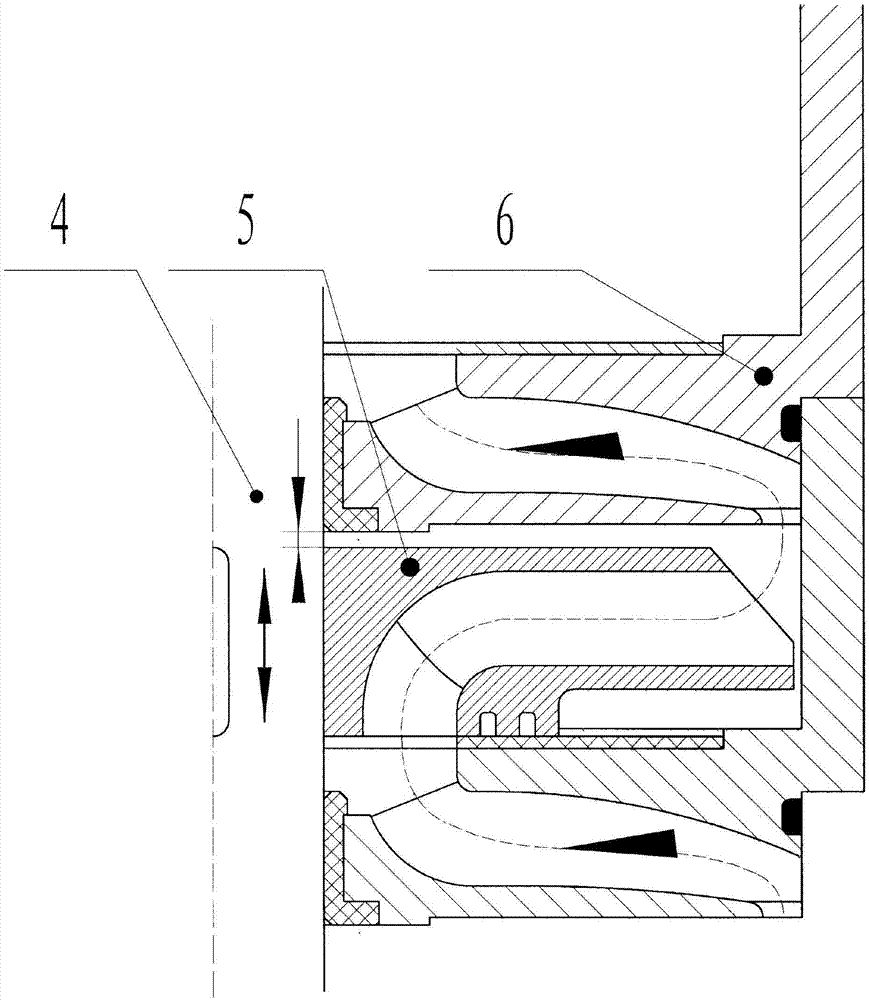
[0026] Attached below Figure 1-2 An embodiment of the present invention is described.

[0027] A high-lift floating impeller well submersible electric pump, the electric pump has a water inlet section 3, the upper end of the submersible motor 2 is fixed on the lower end surface of the water inlet section 3, the lower end is fixed on the base 14, the pump shaft 4 The lower end passes through the water inlet section 3 and is connected to the main shaft of the submersible motor 2 through the coupling 1. The connecting seat 11 is set on the pump shaft 4 and fixedly installed on the upper end surface of the water inlet section 3, and the inner cavity of the connecting seat 11 has a The water hole corresponds to the water outlet of the water inlet section 3; the first-stage impeller 5 is set on the pump shaft 4 through a key connection and is located in the inner cavity of the connection seat 11 and can move axially along the pump shaft 4, and the first The water inlet of the stag...


PUM


Abstract

The invention relates to a submersible electric pump for a high-lift floating impeller well; a submersible motor is fixedly arranged on the lower end of a water inlet joint; a connecting seat is fixedly arranged on the upper end of the water inlet joint; a first stage of impeller is arranged in the inner cavity of the connecting seat; a first stage of diversion shell is arranged on the connecting seat; a second stage of impeller is arranged in the inner cavity of the first stage of diversion shell; a second stage of diversion shell is arranged on the first stage of diversion shell; a third stage of impeller is arranged in the inner cavity of the second stage of diversion shell; a final stage of impeller is arranged in the inner cavity of the previous stage of diversion shell; a last stage of diversion shell is arranged on the previous stage of diversion shell; the impellers are connected and sleeved on a pump shaft through keys and can trip along the axial direction of the pump shaft; a water outlet seat is arranged on the last stage of diversion shell; and the water inlet joint, the connecting seat, the diversion shells and the water outlet seat are tightened, fixed and sealed through tiepieces, and the tripping gaps of the impellers are reserved between the upper end surfaces of the impellers and the lower end surfaces of the diversion shells. According to the submersible electric pump for the high-lift floating impeller well, the automatic balance of axial force is realized, the operation is stable and reliable, the service life of the motor is prolonged, and the efficiency and the single-stage lift of the water pump are improved.

Description

technical field [0001] The invention belongs to the technical field of submersible electric pumps for wells, and in particular relates to a high-lift floating impeller submersible electric pump for wells. Background technique [0002] The existing submersible pumps for wells are composed of submersible motors, water inlet joints, impellers, guide vanes, pump casings, pump shafts, water outlet seats and other components. When working, the pump shaft transmits the power of the motor to the impeller. The work done by the impeller transmits the water flow through the guide vane to the next impeller. There are following defects: [0003] 1. Since the impeller adopts an axially fixed and step-by-step compression structure, the single-stage impeller does not have the ability to adjust up and down by itself. During operation, the pressure difference generated by the front and rear cover plates of the impeller generates an axial force, which is transmitted to the motor step by step,...

Claims


Application Information

Patent Timeline
Patent Type & Authority Patents(China)
IPC IPC(8): F04D13/10F04D29/22F04D29/44
Inventor 侯波彭毅信王君康海娟葛丽珍
Owner 陕西扶龙机电制造有限公司
Learn More