Spin forming element for air-jet spinning machine with insert and associated spinneret

An air-jet spinning machine and spinneret technology, applied in the field of spinning forming elements, can solve problems such as unfavorable yarn ends

Active Publication Date: 2017-10-31
MASCHINENFABRIK RIETER AG
View PDF1 Cites 0 Cited by
  • Summary
  • Abstract
  • Description
  • Claims
  • Application Information

AI Technical Summary

Problems solved by technology

[0005] The disadvantage of the above-described solution is that the air flow discharged through the exhaust opening also inevitably enters the swirl chamber, which creates an air flow that is not conducive to the discharge of the yarn end

Method used


Image

  • Spin forming element for air-jet spinning machine with insert and associated spinneret
  • Spin forming element for air-jet spinning machine with insert and associated spinneret
  • Spin forming element for air-jet spinning machine with insert and associated spinneret

Examples


Embodiment Construction

[0037] As mentioned earlier, there are multiple parts of the same type in the diagram (e.g. Figure 1 to Figure 4 The plate 10 in ), generally only one of a plurality of parts of the same type is marked with a reference numeral to ensure its clarity.

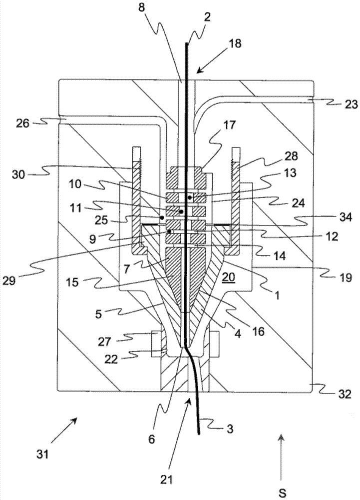
[0038] figure 1 Shown is a spinneret 31 (generally comprising a plurality of corresponding spinnerets 31 ) of an air-jet spinning machine designed according to the invention. The spinneret 31 has a housing 32 with a feed opening 21 through which the fiber bundle 3 (for example conveyed by the pre-stored drawing equipment of the spinneret 31 ) is conveyed into the vortex chamber 20 internally surrounded by the vortex inner wall 19 .

[0039] A plurality of air nozzles 22 are installed in the vortex chamber 20, and they are supplied with compressed air through an annular channel 27 connected to an air pressure source. With the aid of the air flow into the vortex chamber 20 (preferably tangential inflow), a spinning composition ...


PUM

PropertyMeasurementUnit
heightaaaaaaaaaa

Abstract

The invention discloses a spun-forming element (1) for an air-jet spinning machine which produces a yarn (2) from a fiber bundle (3) by means of an air flow, wherein the spun-forming element (1) has a spinning tip (4) with an inlet (6) surrounded by the outer surface (5) of the spinning tip (4) where the yarn (2) is produced with the aid of air flow . According to the invention, the spun-forming element (1) has an internal insert (7) with an outlet channel (8) for the yarn (2) next to the air inlet (6) and multiple An air outlet (9) diverging from the side of the yarn outlet passage (8), so that the airflow introduced into the yarn outlet passage (8) against the spinning direction (S) can partly pass through the outlet (9) ) and partially through the inlet (6). The invention also provides further textile machines with corresponding spun-forming elements (1).

Description

technical field [0001] The invention relates to a spun-forming element for an air-jet spinning machine (Luftspinnmaschine), which produces yarn from a fiber bundle (Faserverband) by means of an air flow, wherein the spun-forming element has a spinning Yarn tip (Spinnspitze), the inlet is surrounded by the outer surface of the spinning tip where the yarn is produced with the aid of air flow. To this end, for an air-jet spinning machine for producing yarn from a fiber bundle with the aid of an air flow, the invention provides such a spinneret with a swirl chamber (Wirbelkammer) with a fiber bundle The feed inlet, and the swirl chamber is partially surrounded by the swirl chamber wall (Wirbelkammerwandung); the spinneret also has a spinning forming element, which at least partially extends into the swirling chamber; wherein the swirling chamber is on the outer surface of the spinning forming element The direction is aligned with the installation of air nozzles, through which air...

Claims


Application Information

Patent Timeline
Patent Type & Authority Patents(China)
IPC IPC(8): D01H4/02
CPCD01H1/115D01H4/02
Inventor M·库布勒
Owner MASCHINENFABRIK RIETER AG
Why Eureka
Try Eureka