Medium-wave infrared laser power stabilizing apparatus and stabilizing method

A technology of infrared laser and stabilization method, which is applied in lasers, laser components, optics, etc., can solve the problems of stable control of laser power in the mid-wave infrared band, and achieve the effect of improving performance and reliability

Inactive Publication Date: 2014-05-07
THE 41ST INST OF CHINA ELECTRONICS TECH GRP
View PDF6 Cites 6 Cited by
  • Summary
  • Abstract
  • Description
  • Claims
  • Application Information

AI Technical Summary

Problems solved by technology

[0014] The existing technology does not solve the problem of stable control of laser power in the mid-wave infrared band, and there are few studies in the mid-infrared band. The purpose of the present invention is to fill the gap in domestic research on the stability control of mid-wave infrared laser power

Method used


Image

  • Medium-wave infrared laser power stabilizing apparatus and stabilizing method

Examples


Embodiment 1

[0030] The stabilizing method of the mid-wave infrared laser power stabilizing system of the present invention mainly comprises the following steps:

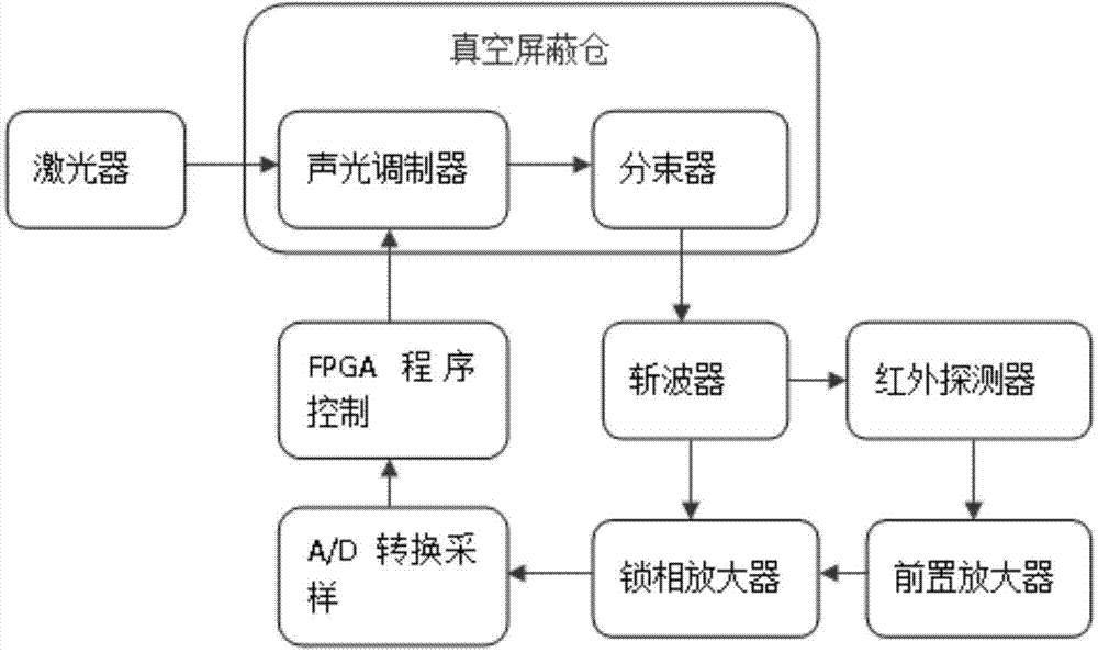
[0031] When ultrasonic waves pass through the acousto-optic crystal, the refractive index of the crystal changes periodically. When the ultrasonic wave meets certain conditions, the acousto-optic crystal is like a bulk grating. The OPO laser is used as a laser light source, and its laser light is incident on the acousto-optic crystal under the action of ultrasound at the Bragg angle, resulting in Bragg diffraction, and its diffraction efficiency is a fixed function relationship with the voltage loaded on the transducing crystal that generates ultrasound; The beam splitter splits the light into two paths, and one path is converted into an electrical signal through the InSb infrared detector. Since the noise in the middle and foreign bands is relatively serious, a suitable chopper and a lock-in amplifier are selected to suppress th...

Embodiment 2

[0041] On the basis of the foregoing embodiments, the present invention is further described, as figure 1 As shown, a medium-wave infrared laser power stabilization device, which includes an optical parametric oscillator laser, an acousto-optic modulator, a beam splitter, an optical chopper, an infrared detector, a preamplifier, a lock-in amplifier, a conditioning circuit, A / D converter, FPGA program control unit and D / A converter, the acousto-optic modulator and the beam splitter are arranged in a vacuum shielding chamber; the optical parametric oscillation laser generates tunable mid-infrared laser through the acousto-optic The modulator produces Bragg diffraction, the diffracted light is split by the beam splitter, one light is output, and the other light is respectively passed through the optical chopper, infrared detector, preamplifier and lock-in amplifier to complete the photoelectric conversion, output the electrical signal, and convert the electrical signal After the ...


PUM

PropertyMeasurementUnit
Wavelengthaaaaaaaaaa

Abstract

The invention provides a medium-wave infrared laser power stabilizing apparatus and stabilizing method. The apparatus comprises a light parameter oscillation laser, an acousto-optic modulator, a beam splitter, an optical chopper, an infrared detector, a front amplifier, a phase-lock amplifier, a conditioning circuit, an A / D converter, an FPGA program control unit and a D / A converter. The acousto-optic modulator and the beam splitter are arranged in a vacuum shield chamber; the light parameter oscillation laser generates a tunable middle infrared laser and generates Bragg diffraction through the acousto-optic modulator; and after diffracted light is subjected to light splitting of the beam splitter, one path of light is outputted, and the other path of light respectively passes through the optical chopper, the infrared detector, the front amplifier and the phase-lock amplifier to finish photoelectric conversion. By using such a scheme, the stable control of laser power within a middle infrared wave band is realized, thus filling the gap in domestic research on medium-wave infrared laser power stabilization control.

Description

technical field [0001] The invention belongs to the technical field of laser power stabilization, and in particular relates to a mid-wave infrared laser power stabilization device and a stabilization method. Background technique [0002] With the development of science and technology and the deepening of research, especially the invention of the cryogenic radiometer, the uncertainty of the optical radiometer has been improved to the order of 10-5, which puts forward high requirements on the stability of the power of the light source to be measured. Lasers were chosen for their collimation, monochromaticity, and high power density. The power stability of the general laser itself is in the range of a few percent, and it cannot be used directly. Certain power stabilization measures need to be taken to make the power stability match the level of the cryogenic radiometer. There are two main ways to stabilize the laser power. One is to stabilize the laser power on the laser itsel...

Claims


Application Information

Patent Timeline
IPC IPC(8): H01S3/13G02F1/35
Inventor 刘玉龙史学舜孙权社杨乐臣刘长明赵坤
Owner THE 41ST INST OF CHINA ELECTRONICS TECH GRP
Why Eureka
Try Eureka