


Quick Research
Generate reliable direction feasibility study reports for your R&D in just a few steps.

Technical Q&A
Discover and master advanced knowledge NOW. Basics, ideas, possibilities, all at once.

Find Solutions
As an expert in R&D theories, this can generate solutions to your technical problems instantly.

Evaluate Feasibility
Analyze your overall solution with one click, know your potential R&D risks in advance.

Monitor Landscape
Get weekly tech updates, stay abreast of the latest tech innovations and key insights.
A hydraulic slit U-shaped hole slag discharge gas treatment method
A hydraulic slitting, U-shaped technology, applied in gas discharge, earthwork drilling, safety devices, etc., can solve problems such as difficulty in slag discharge
- Summary
- Abstract
- Description
- Claims
- Application Information
AI Technical Summary
Problems solved by technology
Method used
Image

Examples
example 1
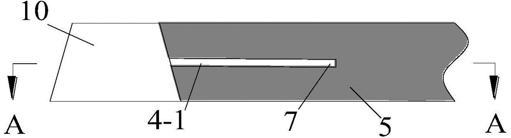
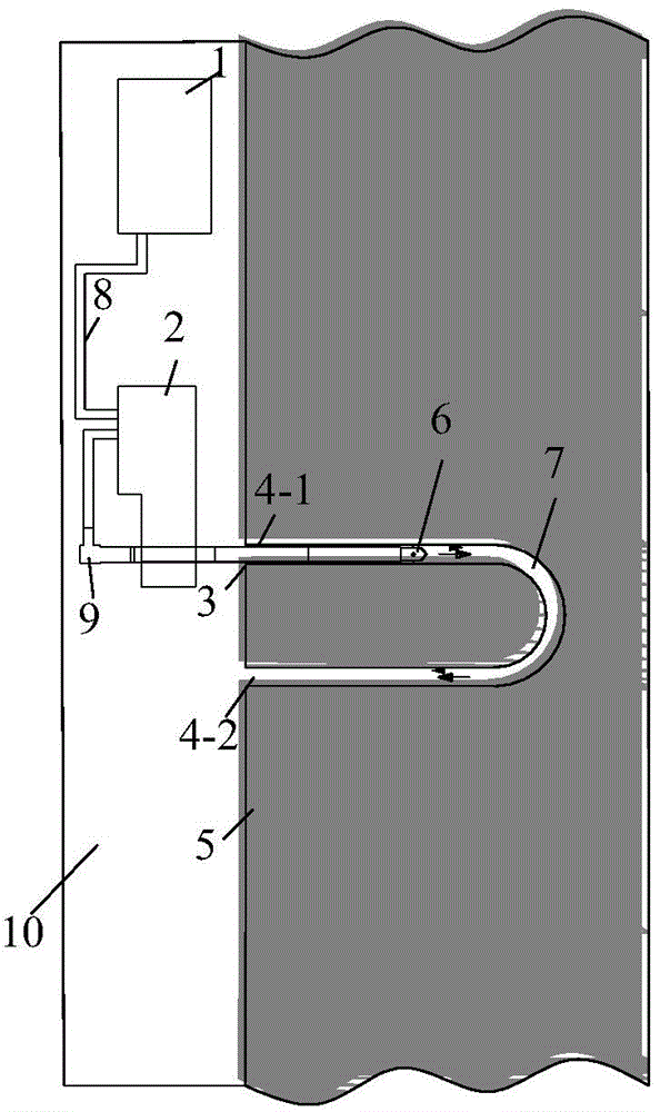
[0030] Such as figure 1 , figure 2 As shown, it is the slag discharge gas treatment of U-shaped drilling holes in the coal seam roadway along the bedding hole hydraulic slotting. Firstly, use a kilometer directional drilling rig to construct a U-shaped borehole 7 with a diameter of 94 mm along the coal seam in the roadway of the coal seam 5 to ensure that the distance between the two side boreholes 4-1 and the borehole 4-2 of the U-shaped borehole 7 is 6 ~8m, then the drilling rig 2 is connected to the hydraulic slotting system 1 through the high-pressure rubber hose 8, the drilling rig 2 is connected to the drill pipe 3 through the high-pressure water braid 9, and the other end of the 75mm drill pipe 3 is connected to the 50mm diameter slotting device 6; Drive the drill pipe 3 to send the slotting device 6 into the slotting drill hole 4-1 to the pre-cutting position, then start the hydraulic slotting system 1, and the high-pressure water flows out from the slotting system 1...
example 2
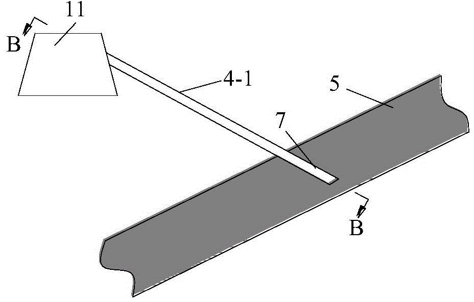
[0032] Such as image 3 , Figure 4 As shown, it is the slag and gas treatment of the high-level roadway 11 through the downhole hydraulic slotting U-shaped drilling 7, which is basically the same as the first example. The different parts are mainly from the high-level roadway 11 of the coal seam 5 to the lower coal seam 5. The hydraulic slotting is carried out in groups and sequentially. First, a U-shaped drill hole with a diameter of 94mm is constructed along the high-level roadway 11 to the lower coal seam 5 to ensure that the U-shaped drill hole has two The distance between side drilling holes is 6-8m, and the depth of U-shaped drilling reaches 3m from the coal seam floor. The remaining parts are the same as Example 1, and the same parts are omitted.
example 3
[0034] Such as Figure 5 , Figure 6 As shown, it is the slag and gas treatment of the low-level roadway 12 through the upward hole hydraulic slotting U-shaped drilling 7, which is basically the same as the first embodiment. The different parts are mainly to implement hydraulic slotting in groups from the low-level roadway 12 through the layer to the upper coal seam 5. Firstly, a U-shaped drill hole with a diameter of 94mm is constructed along the low-level roadway 11 to the upper coal seam 5 to ensure that the U-shaped drill hole has two The distance between side drilling holes is 6-8m, and the depth of U-shaped drilling reaches 3m from the roof of the coal seam. The remaining parts are the same as Example 1, and the same parts are omitted.
PUM
 Abstract
Description
Claims
Application Information
 - R&D Engineer
- R&D Manager
- IP Professional
- Industry Leading Data Capabilities
- Powerful AI technology
- Patent DNA Extraction
Browse by: Latest US Patents, China's latest patents, Technical Efficacy Thesaurus, Application Domain, Technology Topic, Popular Technical Reports.
© 2024 PatSnap. All rights reserved.Legal|Privacy policy|Modern Slavery Act Transparency Statement|Sitemap|About US| Contact US: help@patsnap.com