Eureka AIR delivers breakthrough ideas for toughest innovation challenges, trusted by R&D personnel around the world.

Grouting manipulator

A manipulator and spraying technology, which is applied in shaft lining, tunnel lining, underground chamber, etc., can solve the problems that the construction quality is difficult to be guaranteed, the concrete is easy to rebound and collapse, and the construction efficiency is low, so as to achieve the convenience of spraying height and Adjustment of position, convenience of spraying work and improvement of construction quality

Inactive Publication Date: 2014-05-07
XUZHOU XCMG CONSTR MACHINERY CO LTD BUILDING MACHINERY
View PDF6 Cites 11 Cited by
  • Summary
  • Abstract
  • Description
  • Claims
  • Application Information

AI Technical Summary

Problems solved by technology

[0003] In the concrete spraying process, in most cases, the manual spraying method is still used, that is, the operator holds the spray head and the delivery hose to spray the construction work surface, but this method is difficult to control the spraying quality of the concrete, and the concrete is easy to rebound and collapse. fall, resulting in poor construction quality, low construction efficiency, and high labor intensity for workers
Workers can also use the spraying bracket of the wet spraying machine to assist spraying. This method reduces the labor intensity of workers to a certain extent, but it is still necessary for workers to operate the spray head and adjust the spraying height during the construction process, and the construction quality is still difficult to be guaranteed.
In addition, during the construction process, the operator is relatively close to the construction surface, and is vulnerable to injury to the operator due to the rebound of the falling material on the construction surface.
[0004] In addition to manual spraying, large-scale spraying vehicles can also be used for construction in engineering, which costs a lot of money and is easily limited by the construction space, so it is not suitable for construction in small and medium-sized tunnels
On the other hand, since the spraying truck itself has a complete pumping system, some existing spraying equipment will be idle, wasting the existing resources

Method used


Image

  • Grouting manipulator
  • Grouting manipulator
  • Grouting manipulator

Examples


Embodiment Construction

[0024] The technical solutions of the present invention will be described in further detail below with reference to the accompanying drawings and embodiments.

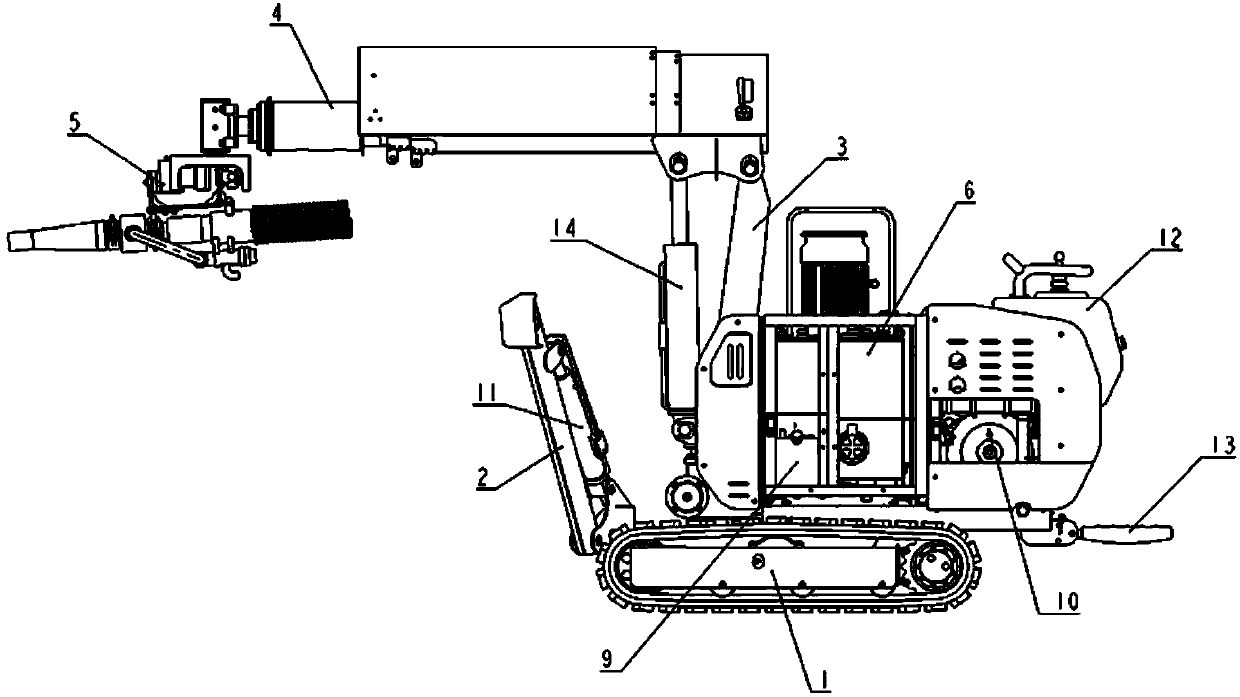
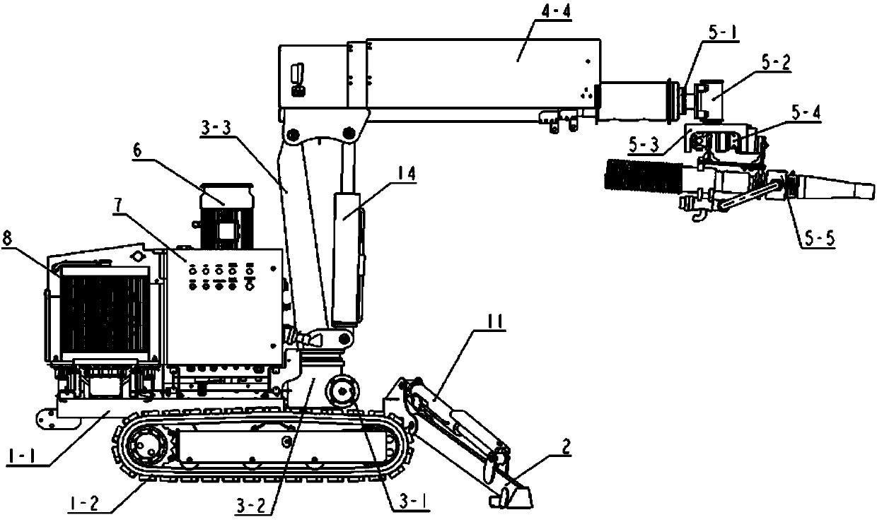
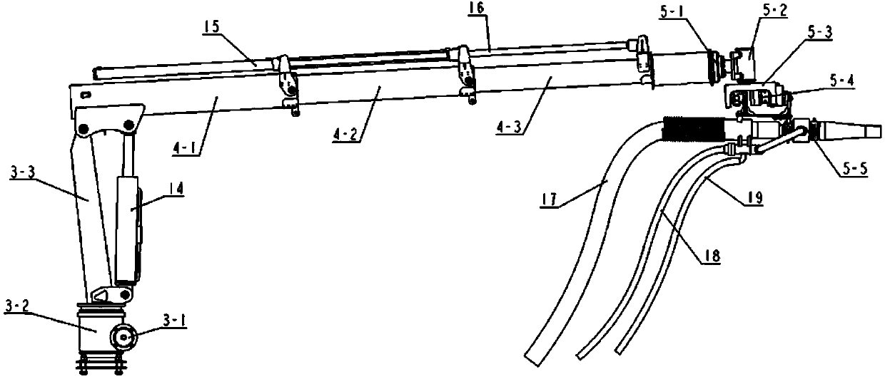
[0025] Such as figure 1 Shown is a schematic structural view of an embodiment of the spraying manipulator of the present invention. In this embodiment, the spraying robot includes a chassis 1 , a slewing mechanism 3 , a boom 4 , a spray head device 5 , a hydraulic system 6 and an electrical system 7 . The slewing mechanism 3 , the hydraulic system 6 and the electrical system 7 are all arranged on the chassis 1 . The arm frame 4 is hinged with the slewing mechanism 3 and can rotate relative to the chassis 1 driven by the slewing mechanism 3. The spray head device 5 is installed on the front end of the arm frame 4 (here, the direction pointing to the working position is forward), and is connected to the wet spraying machine. Concrete conveying pipes, compressed air conveying pipes and quick-setting agent conveying pipe...


PUM


Abstract

The invention relates to a grouting manipulator. The grouting manipulator comprises a chassis, a revolving mechanism, an arm support, a spray head device, a hydraulic system and an electric system, wherein the revolving mechanism, the hydraulic system and the electric system are arranged on the chassis; the arm support is hinged to the revolving mechanism, and can be driven to rotate relative to the chassis by using the revolving mechanism; the spray head device is arranged at the front end of the arm support, and is connected with a concrete conveying pipe, a compressed air conveying pipe and a setting accelerator conveying pipe of a wet sprayer; the electric system and the hydraulic system are used for controlling the actions of the arm support and the spray head device. By adopting the grouting manipulator, efficient matching with the wet sprayer is realized, operating personnel can carry out grouting work conveniently, the spray height and position can be adjusted conveniently, heavy labor work of manual holding of a spray head is liberated, the spray range is enlarged, and the construction quality is improved. Compared with a large-sized grouting vehicle, the grouting manipulator has the advantages of simple structure, small size, lower cost, suitability for construction of certain medium and small-section tunnels, and more extensive application occasions.

Description

technical field [0001] The invention relates to the field of engineering machinery, in particular to a spraying manipulator. Background technique [0002] At present, concrete spraying construction technology is divided into two types: dry spraying method and wet spraying method. However, dry spray technology has disadvantages such as high rebound rate, large dust, unguaranteed spray intensity and serious health hazards to operators, and is gradually being replaced by wet spray technology. Wet spraying technology refers to the use of compressed air to transport the ready-mixed concrete mixture to the nozzle through the pipeline, form a bundle after being mixed with an accelerator, and spray it at a high speed to the sprayed surface to condense and harden, thereby forming a concrete support layer. [0003] In the concrete spraying process, in most cases, the manual spraying method is still used, that is, the operator holds the spray head and the delivery hose to spray the co...

Claims


Application Information

Patent Timeline
IPC IPC(8): E21D11/10
Inventor 冯敏贾文彬张卫国许爱斌
Owner XUZHOU XCMG CONSTR MACHINERY CO LTD BUILDING MACHINERY
Why Eureka
Eureka Blog
Learn More