Eureka AIR delivers breakthrough ideas for toughest innovation challenges, trusted by R&D personnel around the world.

frame beam

A frame beam and frame technology, which is applied to vehicle parts, upper structure, upper structure sub-assembly, etc., can solve problems such as the influence of handling stability, development workload, and increased manufacturing cost, and achieve the effect of simple structure

Active Publication Date: 2016-08-10
MITSUBISHI MOTORS CORP
View PDF7 Cites 0 Cited by
  • Summary
  • Abstract
  • Description
  • Claims
  • Application Information

AI Technical Summary

Problems solved by technology

Therefore, in addition to the collision requirements, functions such as steering stability and vibration of the vehicle are also affected, and readjustment is required, which increases the development effort and manufacturing cost.

Method used


Image

  • frame beam
  • frame beam
  • frame beam

Examples


Embodiment Construction

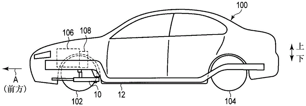
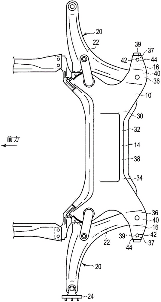
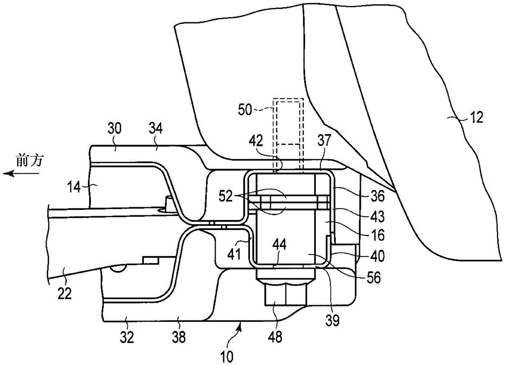
[0026] Hereinafter, a cross member according to one embodiment of the present invention will be described. figure 1 It is a side view showing a vehicle 100 including a suspension cross member 10 as a frame cross member according to an embodiment of the present invention, figure 2 is a plan view showing the suspension beam 10, image 3 is a side view showing the mounting portion 16 of the suspension beam 10, Figure 4 is a perspective view showing the mounting portion 16 of the suspension beam 10, Figure 5 is a plan view showing the mounting portion 16 of the suspension beam 10, Figure 6 is a side view showing the suspension beam 10, Figure 7 It is a perspective view showing a part of the suspension beam 10 .

[0027] figure 1 A vehicle 100 equipped with a cross member 10 is shown. Vehicle 100, figure 1 The direction of the arrow A indicated by is the front, and the front wheel 102 is provided in the front of the vehicle 100, and the rear wheel 104 is provided in the...


PUM


Abstract

The invention provides a cross member which can simply and easily adjust a separated load of an installation part. A suspension cross member (10) comprises a main body (14) extending in the width direction of a vehicle, and a installation part (16), wherein the installation part (16) has a hollow structure and is arranged on the main body part (14) and connected with a side frame (12). The suspension cross member (10) also comprises an installation bolt (48) used for fastening the installation part (16) on the side frame (12), a cylinder (56) arranged in the installation part (16), and a reinforcement plate (52). The cylinder (56) has a through cylinder hole (54), the through cylinder hole (54) and the cylinder (56) pass through the reinforcement plate (52), and the reinforcement plate (52), the cylinder (56) and the through cylinder hole (54) are installed in the installation part (16). In addition, the number of the reinforcement plates (52) can be adjusted, and the separated load of the installation part (16) can be adjusted.

Description

technical field [0001] The present invention relates to an off-load cross member of an adjustable mounting portion. Background technique [0002] As a frame cross member, for example, a suspension cross member of a vehicle is known. The suspension cross member is a component that holds the suspension device (suspension mechanism), and is fixed to the side member by fastening bolts. The side sill is a member constituting the frame of the vehicle, and is provided below the vehicle in the front-rear direction, and an engine, a transmission, and the like are attached to the side sill. [0003] Vehicles have a crash zone that typically deforms during a crash to absorb the energy of the crash. In addition, the suspension cross member is configured such that when a predetermined or greater impact energy is applied, the mounting portion is damaged and detached from the side member. [0004] As a result, even if an accident occurs in the vehicle and the collision area is deformed,...

Claims


Application Information

Patent Timeline
Patent Type & Authority Patents(China)
IPC IPC(8): B62D25/20
Inventor 新名祐三坂本彻
Owner MITSUBISHI MOTORS CORP
Why Eureka
Eureka Blog
Learn More