
Read-write structure of single-plate optical module and read-write method

A reading and writing method and optical module technology, applied in the field of switch communication, can solve problems such as lengthening of research and development cycle, increase of production cost, intensification of research and development work, and achieve the effect of reducing research and development work, reducing development hardware cost, and shortening the research and development cycle

Inactive Publication Date: 2014-04-30
PHICOMM (SHANGHAI) CO LTD
View PDF1 Cites 6 Cited by
  • Summary
  • Abstract
  • Description
  • Claims
  • Application Information

AI Technical Summary

Problems solved by technology

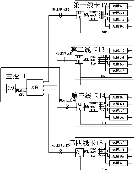
[0008] The application of the above processing method has the following disadvantages: first, there is enough research and development funds to support the increase in production costs caused by adding a CPU to the line card; second, the PCB board of the line card has enough space to place the CPU and its external devices; The third is that the addition of CPU requires software cooperation, which intensifies the research and development work and lengthens the research and development cycle

Method used


Image

  • Read-write structure of single-plate optical module and read-write method
  • Read-write structure of single-plate optical module and read-write method
  • Read-write structure of single-plate optical module and read-write method

Examples


Embodiment Construction

[0033] Specific embodiments of the present invention will be further described below in conjunction with the accompanying drawings.

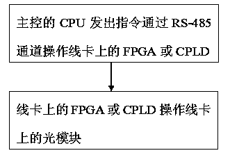
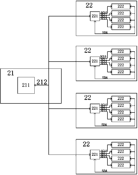
[0034] Such as figure 2 As shown, the present invention discloses a read-write structure of a single-board optical module in a rack-mounted switch based on the RS-485 communication protocol. The structure includes a main control 21 and four line cards 22 respectively communicating with the main control 21 .

[0035] The main control 21 includes: a control module (CPU) 211 and an RS-485 bus 212 connected to the output end of the control module 211 .

[0036] The line card 22 includes a programmable logic module 221 that is electrically connected to the RS-485 bus 212 , and an optical module 222 that is electrically connected to the output of the programmable logic module 221 . Each line card 22 includes four optical modules 222 connected to programmable logic modules 221 respectively. The programmable logic module 221 adopts a field programmab...


PUM


Abstract

The invention discloses a read-write structure of a single-plate optical module. The structure comprises a master control part and a cable clip, wherein the master control part is in communication connection with the cable clip. The master control part comprises a control module and an RS-485 bus in circuit connection with the output end of the control module. The cable clip comprises a programmable logic module and the optimal module in circuit connection with the output end of the programmable logic module, wherein the programmable logic module is in circuit connection with the RS-485 bus. Communication between the control module of the master control part and the programmable logic module is carried out through an RS-485 channel, a CPU on the cable clip and an exchange chip on the master control part are not needed, and therefore equipment development hardware cost is reduced; space of a PCB is saved, and space can be more flexibly provided for the layout of other devices on the cable clip; the equipment response speed is improved, and equipment flexibility is better; because the CPU is not needed, software and drive research and development work is reduced, and accordingly the research and development cycle is shortened, and risks are reduced.

Description

technical field [0001] The invention relates to a switch communication technology, in particular to a read-write structure and a read-write method of a single-board optical module in a rack switch. Background technique [0002] In large-scale switch systems, a large number of different types of optical modules are often used. According to the standards of carrier-grade broadband access equipment, some real-time parameters of optical modules need to be monitored, such as: transmitted optical power, received optical power, temperature, and operating voltage. , laser bias, etc. [0003] For some central office rack-mounted devices, the information of the optical modules on each board is read and written by the CPU on each board. When the CPU of this board obtains the information of the optical modules, Network (Fast Ethernet, FE) and other channels are reported to the main control CPU through the backboard. However, when there are not many services on the single board, adding...

Claims


Application Information

Patent Timeline
Patent Type & Authority Applications(China)
IPC IPC(8): H04L12/931
Inventor 童魏明
Owner PHICOMM (SHANGHAI) CO LTD
Learn More