
Slew rate enhancement circuit applicable to LDO regulators (low dropout regulators)

A slew rate enhancement, circuit technology, applied in the direction of regulating electrical variables, control/regulating systems, instruments, etc., can solve problems such as low quiescent current and fast load transient response, and achieve increased slew rate, improved transient response, The effect of improving output accuracy

Inactive Publication Date: 2014-04-30
HEFEI UNIV OF TECH
View PDF5 Cites 13 Cited by
  • Summary
  • Abstract
  • Description
  • Claims
  • Application Information

AI Technical Summary

Problems solved by technology

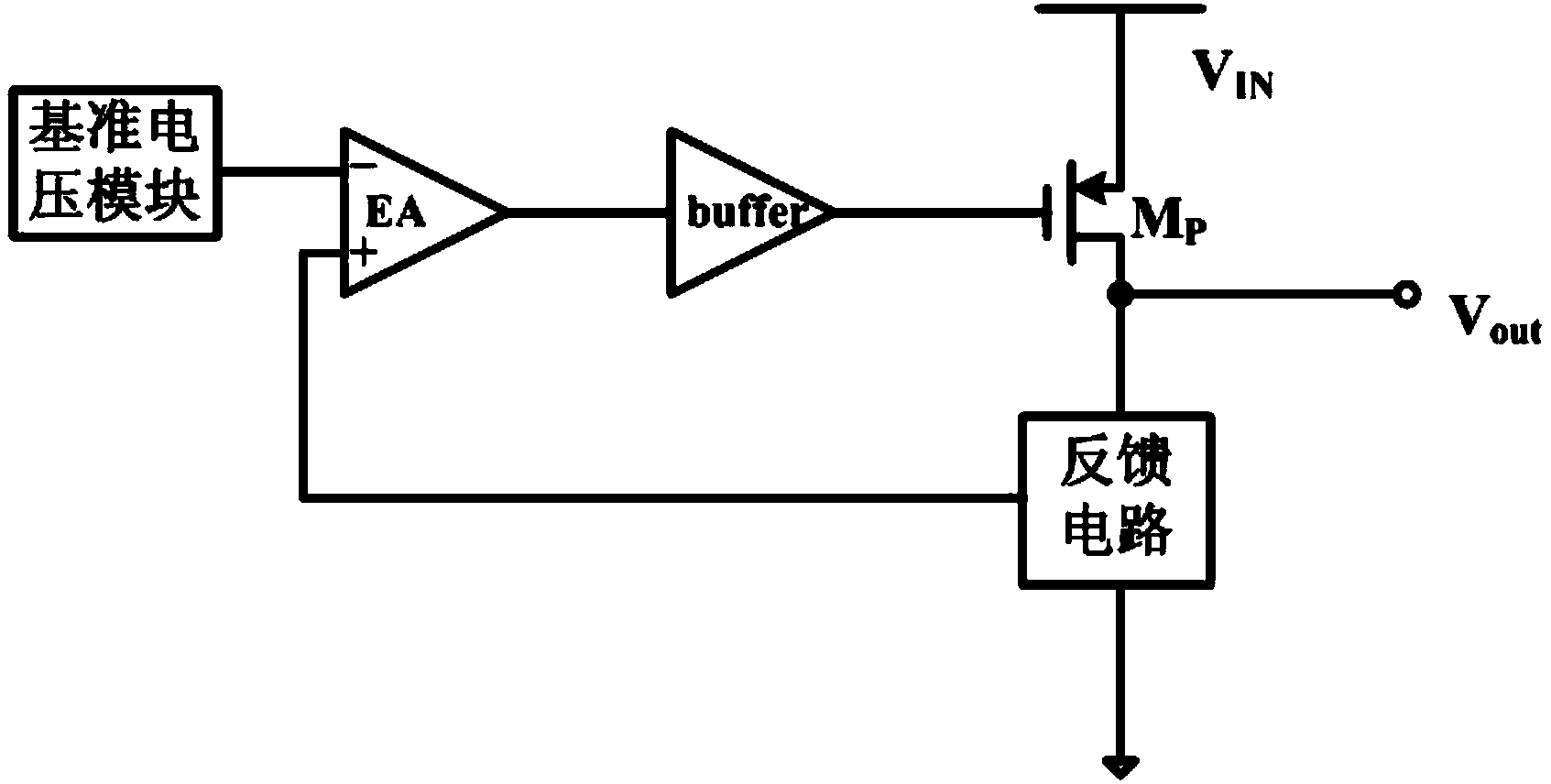
[0003] Traditional LDO circuits such as figure 1 As shown, V out will generate spikes during load transients, V out It takes a certain amount of time to restore stability. To obtain a fast load transient response, a large quiescent current is required to increase the charging and discharging speed of the power regulator gate.
However, in portable applications, it is necessary to extend the battery life as much as possible, and the traditional LDO circuit structure cannot take into account both low quiescent current and fast load transient response.

Method used


Image

  • Slew rate enhancement circuit applicable to LDO regulators (low dropout regulators)
  • Slew rate enhancement circuit applicable to LDO regulators (low dropout regulators)
  • Slew rate enhancement circuit applicable to LDO regulators (low dropout regulators)

Examples


Embodiment Construction

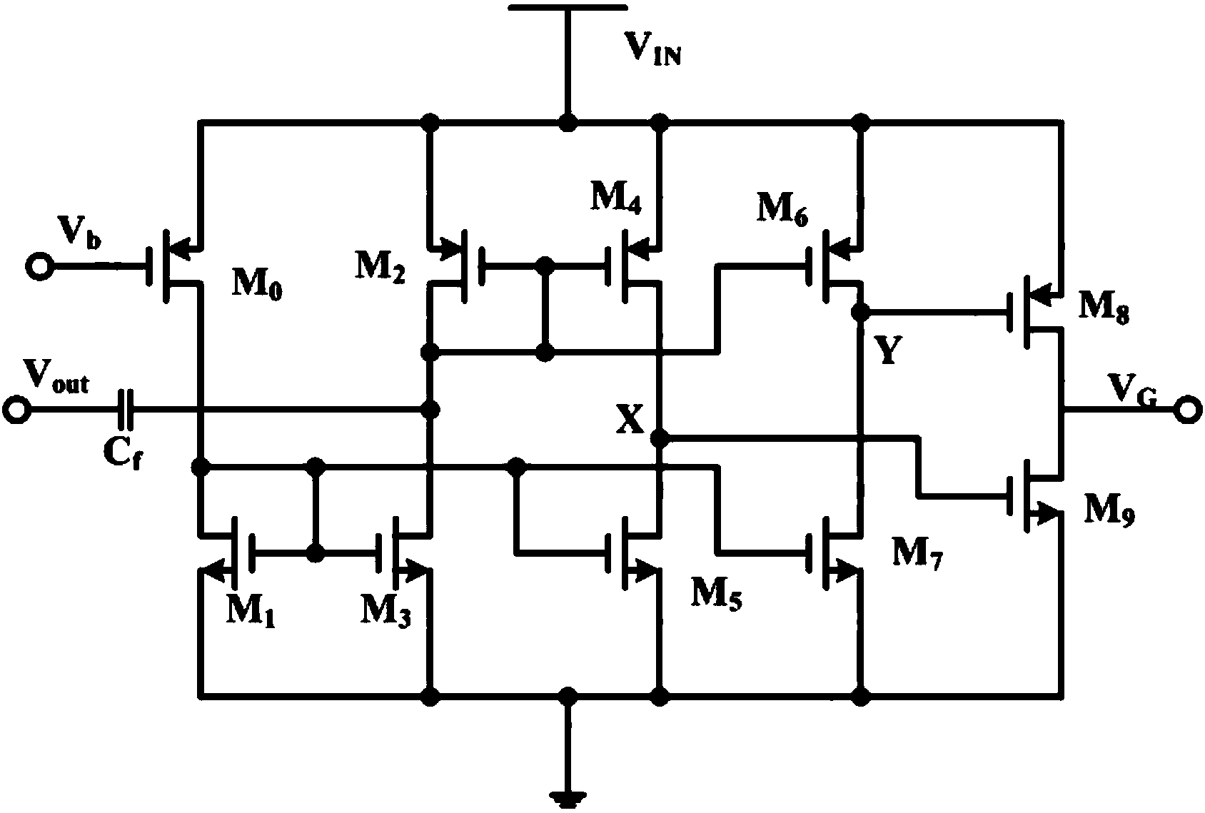
[0023] Such as figure 2 As shown, a slew rate enhancement circuit applied to LDO includes PMOS tube M 0 , M 2 , M 4 , M 6 , M 8 , NMOS tube M 1 , M 3 , M 5 , M 7 , M 9 and capacitance C f ; The capacitance C f One end is the input end of the slew rate enhancement circuit, and the other end is connected to the PMOS transistor M 2 The gate, drain, PMOS transistor M 4 The gate, PMOS transistor M 6 The gate and NMOS tube M 3 the drain connection;

[0024] PMOS tube M 2 The sources are connected with the PMOS transistor M 0 The source, PMOS transistor M 4 The source, PMOS transistor M 6 The source, PMOS transistor M 8 The source is connected, and connected to the external input power supply V IN , PMOS tube M 2 The drain is connected to the NMOS transistor M 3 The drain of the PMOS tube M 2 The gate is connected to the PMOS transistor M4 grid;

[0025] PMOS tube M 4 The drain of the NMOS transistor M 5 The drain and NMOS transistor M 9 connected to the g...


PUM


Abstract

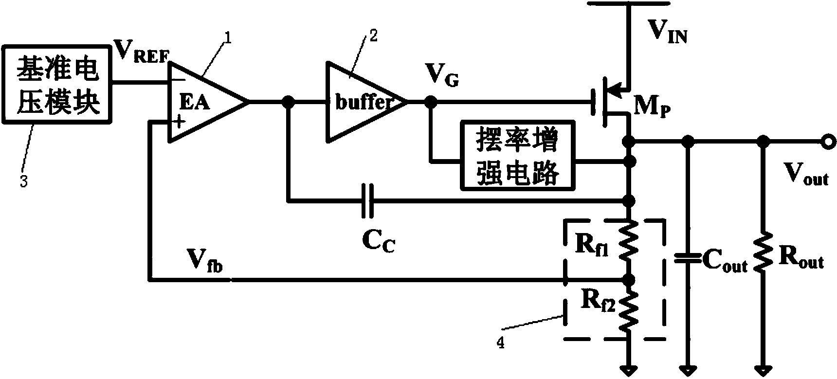
The invention discloses a slew rate enhancement circuit applicable to LDO regulators (low dropout regulators). The slew rate enhancement circuit comprises PMOS (P-channel Metal Oxide Semiconductor) transistors M0, M2, M4, M6 and M8, NMOS (N-channel Metal Oxide Semiconductor) transistors M1, M3, M5, M7 and M9, a bias current source I0, and a capacitor Cf. On the premise of not significantly increasing static power consumption, when LDO load of an LDO regulator, which the slew rate enhancement circuit is integrated to, jumps, changes in output end voltage can be quickly detected and a gate of a power regulating tube is transiently regulated; accordingly, the slew rate of voltage in the gate of the power regulating tube is greatly increased, and transient response of the LDO circuit is improved.

Description

technical field [0001] The invention relates to the technical field of power management, in particular to a slew rate enhancement circuit applied to an LDO. Background technique [0002] Portable devices such as smartphones, personal digital assistants, and handheld devices often require different levels to power different modules. LDO has the advantages of low cost, low output noise, simple circuit structure, and small chip area, and has become an important circuit in power management chips. The essence of LDO is to use the stable voltage generated by the bandgap reference and the negative feedback control loop to obtain an output voltage that basically does not change with the environment. LDOs can convert the decaying battery voltage into a stable and accurate voltage with low noise to meet the needs of noise-sensitive analog modules and radio frequency modules in portable equipment. [0003] Traditional LDO circuits such as figure 1 As shown, V out will generate spik...

Claims


Application Information

Patent Timeline
Patent Type & Authority Applications(China)
IPC IPC(8): G05F1/56
Inventor 陈洋程心解光军杨依忠
Owner HEFEI UNIV OF TECH
Learn More