
Optical cable fiber distribution box

A fiber distribution box and optical cable technology, which is applied in the direction of fiber mechanical structure, etc., can solve the problems of affecting the sealing of the box, box leakage, and increasing the manufacturing cost of the fiber distribution box, and achieves convenient and flexible jumpers, convenient installation, and compact structure Effect

Inactive Publication Date: 2014-04-30
NINGBO TIANXIANG COMM EQUIP
View PDF4 Cites 5 Cited by
  • Summary
  • Abstract
  • Description
  • Claims
  • Application Information

AI Technical Summary

Problems solved by technology

[0002] In the prior art, the fusion splicing and jumper wires in the optical fiber distribution box are generally carried out on the same operation plane. Therefore, the box designed in this way generally must be made very large to meet the requirements, which causes the box during production and processing. Larger molds are required for production, so the manufacturing cost of the fiber distribution box is virtually increased. At the same time, the larger box is placed outdoors for a long time, exposed to wind and rain, and it is easy to deform and cause the box to leak. Affect the sealing of the box, in view of the above problems, how to design a box that will weld and jumper in layers, reduce the volume of the box as small as possible, and make the internal structure of the box compact, has become a problem to be solved

Method used


Image

  • Optical cable fiber distribution box
  • Optical cable fiber distribution box
  • Optical cable fiber distribution box

Examples


Embodiment Construction

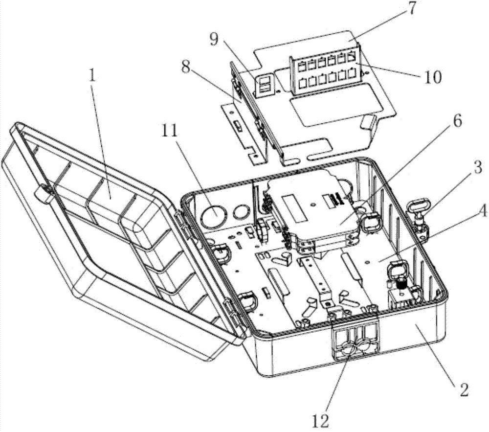
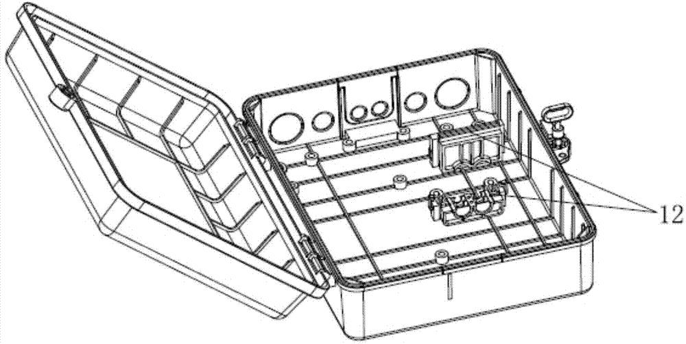
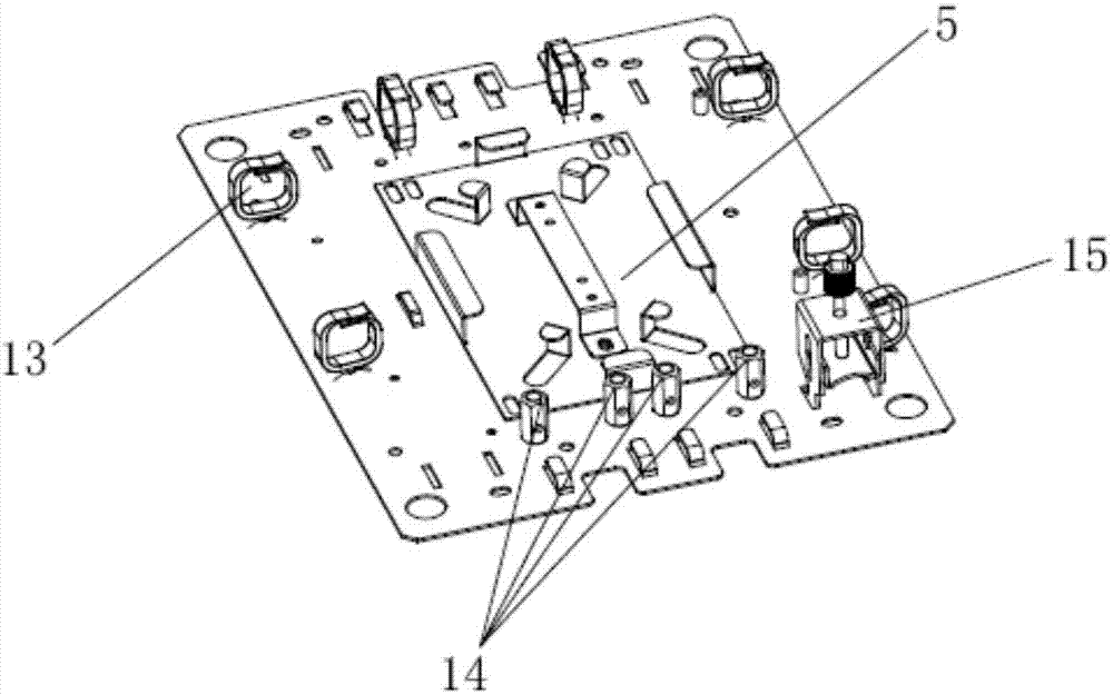
[0018] Attached below figure 1 to attach image 3 The technical solutions of the present invention are further described through specific implementation methods.

[0019] An optical fiber distribution box, comprising a box body 2 and a box cover 1 hinged to the box body 2, one side of the box body 2 and the box cover 1 is provided with a lock for locking the box body 2 and the box cover 1 Tightening device 3, a detachable inner plate 4 is fastened on the inner bottom surface of the box body 2, an optical fiber fusion splicing area and an optical cable storage area are arranged on the inner plate 4, and a fiber storage plate 5 is arranged on the optical fiber fusing area The fiber storage plate 5 is provided with a superimposed and reversible fusion splice tray 6, the top of the fusion splice tray 6 is provided with a reversible upper layer plate 7, and one side of the upper layer plate 7 is provided with a locking structure, so The other side of the upper deck 7 is provided ...


PUM


Abstract

The invention discloses an optical cable fiber distribution box. A detachable inner plate is fastened to the bottom face in the box body, stackable and turnable fusion welding disks are arranged on a fiber storage plate, a turnable upper layer plate is arranged on the top of the fusion welding plates, an optical fiber berthing space plate used for berthing optical fibers which do not enter homes yet is arranged on the top face of the upper layer plate, a mounting support used for an optical fiber adapter to be inserted in is arranged on one side of the optical fiber berthing space plate, and a filer inlet hole and a fiber outlet hole are formed in the portions, on the front and the back of the mounting support of the adapter, of the upper layer plate. The detachable inner plate can be placed outside the box body for mounting the optical fibers, the optical fibers can be welded conveniently in a fusion mode and the number of cores of the connected-in optical fibers can be expanded conveniently because the stackable and turnable fusion welding disks are arranged on the fiber storage plate, wire jumping and fusion welding can be carried out in a layered mode because the upper layer plate, the optical fiber berthing space plate and the mounting support of the adapter are arranged, and meanwhile the wire jumping can be more convenient and flexible to carry out. The optical cable fiber distribution box is compact in structure and convenient to install, and the optical fibers are high in connecting-in quality and flexible to connect in.

Description

technical field [0001] The invention relates to the technical field of communication equipment, in particular to an optical fiber distribution box. Background technique [0002] In the prior art, the fusion splicing and jumper wires in the optical fiber distribution box are generally carried out on the same operation plane. Therefore, the box designed in this way generally must be made very large to meet the requirements, which causes the box during production and processing. Larger molds are required for production, so the manufacturing cost of the fiber distribution box is virtually increased. At the same time, the larger box is placed outdoors for a long time, exposed to wind and rain, and it is easy to deform and cause the box to leak. Affecting the airtightness of the box, in view of the above problems, how to design a box with layered operation of welding and jumper, reduce the volume of the box as small as possible, and make the inner structure of the box compact, has...

Claims


Application Information

Patent Timeline
Patent Type & Authority Applications(China)
IPC IPC(8): G02B6/44
Inventor 胡翱翔金兴弟
Owner NINGBO TIANXIANG COMM EQUIP
Learn More