Airflow harrow type sludge dryer

A sludge drying and rake technology, applied in the direction of dewatering/drying/concentrating sludge treatment, can solve the problems of increasing the processing capacity, increasing the power consumption of the dryer, and high operating costs, eliminating the possibility of deflagration and increasing pollution. The effect of reducing mud drop height and running cost

Active Publication Date: 2015-07-08
SOUTHEAST UNIV
View PDF6 Cites 0 Cited by
  • Summary
  • Abstract
  • Description
  • Claims
  • Application Information

AI Technical Summary

Problems solved by technology

The drum dryer mainly has the following technical problems: First, due to the rotation of the shell, it is easy to leak air, which increases the oxygen content of the drying medium. For the drying of sludge whose combustion performance is similar to that of lignite and its volatility is higher than that of lignite, it increases The possibility of deflagration; second, because the drying medium can only enter from the axial direction, in order to meet sufficient gas-solid contact time, the diameter and length of the device are large, the equipment is heavy, the equipment cost is high, the heat loss is high, and the drying heat efficiency is low; Third, due to the rotation of the shell, waste heat cannot be used to indirectly heat the sludge to improve drying thermal efficiency and reduce investment and operating costs
The airtightness of the fluidized bed dryer is better than that of the drum dryer, but the air flow resistance is large and the operating cost is high
[0003] The existing rake dryer mainly relies on the heat conduction of the wall surface, which has low thermal efficiency and high energy consumption for sludge drying
Intermittent operation is mostly used, and continuous operation is not possible, which increases the operating cost
The sealing of the device is not good, and there will be a safety risk when drying sludge with high volatile content
In the sludge drying viscous zone, the heat and mass transfer resistance increases sharply, the thermal efficiency of the dryer is low, and the power consumption of the dryer is increased at the same time
The contact time between the material and the drying medium is short, and the sludge treatment volume is small. In order to increase the treatment volume and reduce the moisture content of the product, it is necessary to increase the size of the dryer, which increases the cost accordingly.

Method used


Image

  • Airflow harrow type sludge dryer
  • Airflow harrow type sludge dryer
  • Airflow harrow type sludge dryer

Examples


Embodiment Construction

[0020] The present invention will be further described below in conjunction with the accompanying drawings.

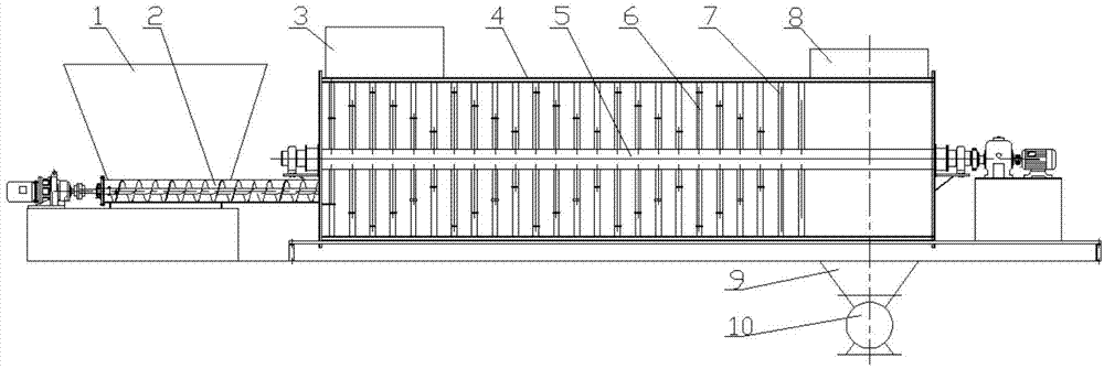
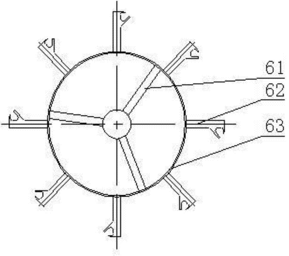
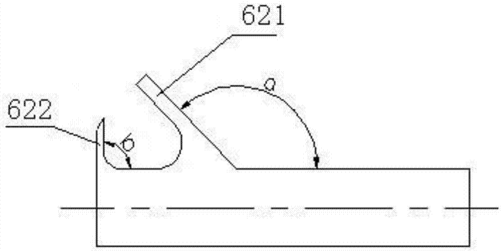
[0021] as attached figure 1 and 4 As shown, the airflow rake sludge dryer includes a circular cylindrical shell 4 with a fixed position, and a rotating shaft 5 coaxial with the shell 4 is installed in the center of the shell 4, and the rotating shaft 5 can be driven by the power device Rotate down, at least one set of incremental stirring blades, several sets of decreasing stirring blades and straight stirring blades 7 are fixedly installed on the rotating shaft 5, and the incremental stirring blades are arranged on the housing 4 On the front side of the housing 4, the set of descending stirring blades is arranged in the middle of the housing 4, and the straight stirring blades 7 are arranged on the rear side of the housing 4. as attached figure 2 As shown, each of the stirring blade groups includes more than two transition ring stirring blades 6, and the transitio...


PUM


Abstract

The invention discloses an airflow harrow type sludge dryer which comprises a cylindrical shell with a fixed position, wherein a rotating shaft coaxial with the shell is arranged at the center of the shell, at least one progressive increase stirring blade set, a plurality of progressive decrease stirring blade sets and a straight stirring blade are fixedly arranged on the rotating shaft, each stirring blade set comprises more than two transition ring stirring blades, the transition ring stirring blades are coaxially fixed on the rotating shaft, each transition ring stirring blade comprises a plurality of supporting ribs, a plurality of shoveling plates and transition rings, the transition rings are connected to the rotating shaft through the supporting ribs, the shoveling plates are uniformly distributed and connected to the circumferences of the transition rings, the diameters of the transition rings of the progressive increase stirring blade set are sequentially progressively increased, and the diameters of the transition rings of the progressive decrease stirring blade sets are sequentially decreased. The airflow harrow type sludge dryer has the characteristics of low resistance, high drying efficiency, difficulty in caking of sludge, and compact structure, and is capable of continuously running, and meets the requirement of safety during sludge drying.

Description

technical field [0001] The invention relates to a rake drying device, in particular to an airflow rake drying device for treating sludge. Background technique [0002] At present, most of the sludge drying adopts drum dryer or fluidized bed dryer. The drum dryer mainly has the following technical problems: First, due to the rotation of the shell, it is easy to leak air, which increases the oxygen content of the drying medium. For the drying of sludge whose combustion performance is similar to that of lignite and its volatility is higher than that of lignite, it increases The possibility of deflagration; second, because the drying medium can only enter from the axial direction, in order to meet sufficient gas-solid contact time, the diameter and length of the device are large, the equipment is heavy, the equipment cost is high, the heat loss is high, and the drying heat efficiency is low; Third, due to the rotation of the shell, waste heat cannot be used to indirectly heat t...

Claims


Application Information

Patent Timeline
Patent Type & Authority Patents(China)
IPC IPC(8): C02F11/12
Inventor 葛仕福赵培涛
Owner SOUTHEAST UNIV
Why Eureka
Try Eureka