Electric spanner

A wrench and time technology, applied in the field of electric wrenches, can solve the problems of non-adjustable striking force and irreducible striking force of striking screws, and achieve the effects of adjustable striking time, stable and solid parts, and strong operability.

Inactive Publication Date: 2014-04-30
浙江立邦电器有限公司
View PDF6 Cites 0 Cited by
  • Summary
  • Abstract
  • Description
  • Claims
  • Application Information

AI Technical Summary

Problems solved by technology

The invention adopts the pawl pressing plate to replace the separation and closing of the cylindrical pin and the pawl in the background technology, so that the ratchet interval generates impact torque, which improves the impact torque of the electric wrench and improves the operation stability and reliability of the electric wrench; the large gear and The use of the clutch and the clutch spring between the ratchet seat, when the torque the ratchet bears is greater than the rated torque, the clutch spring clamped between the clutch and the large gear will generate greater compression to limit the relative movement of the clutch, thereby The output torque of the ratchet is limited within the rated torque, which provides overload protection for the electric wrench; but this invention patent also has the technical problem that the striking force cannot be adjusted
[0004] The above prior art does not solve the problem that the size of the striking force of the striking screw of the electric wrench cannot be adjusted

Method used


Image

  • Electric spanner
  • Electric spanner
  • Electric spanner

Examples


Embodiment 1

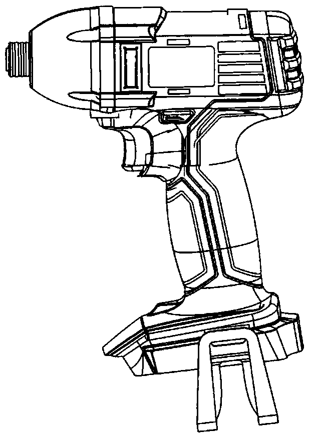
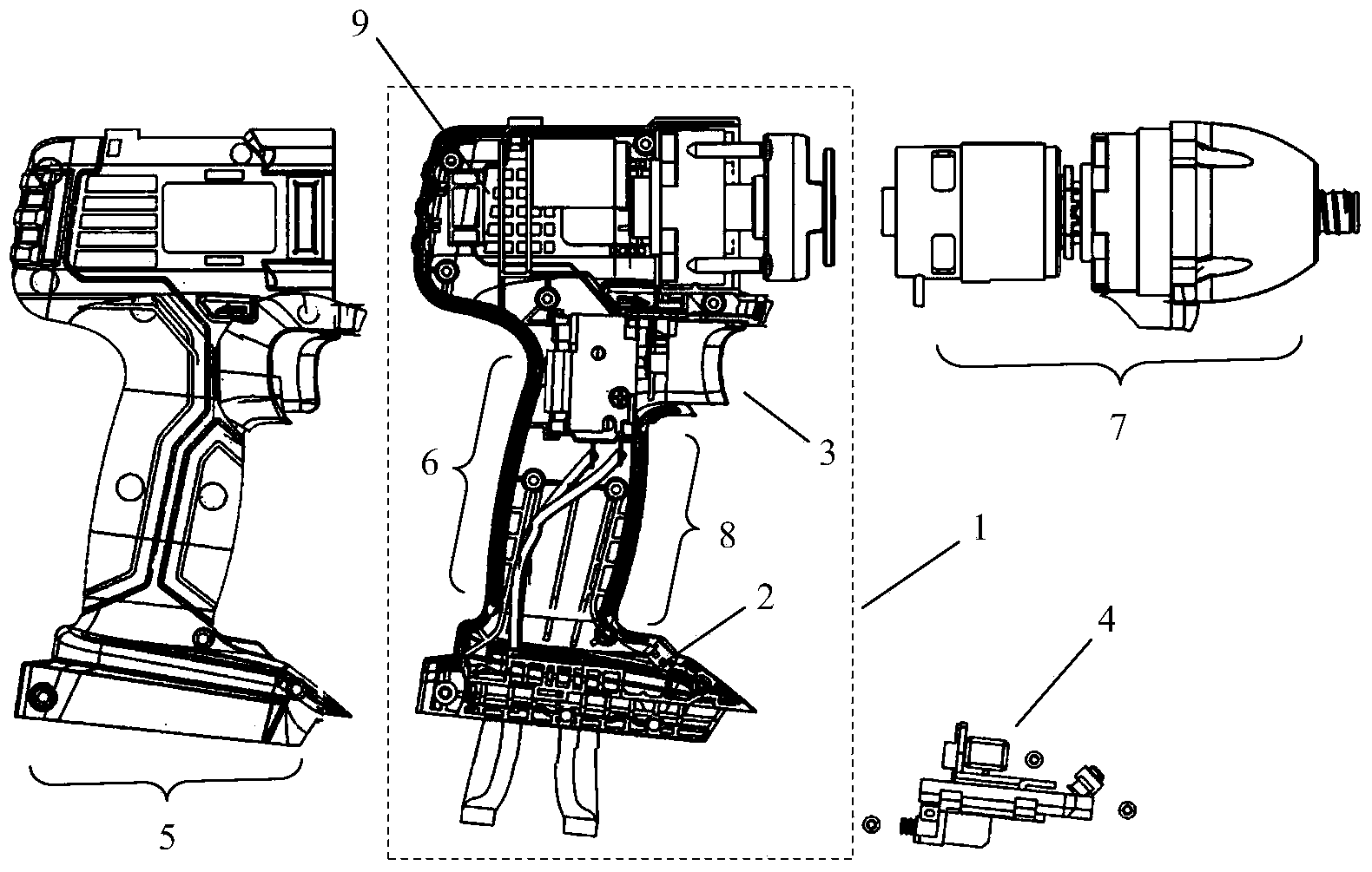
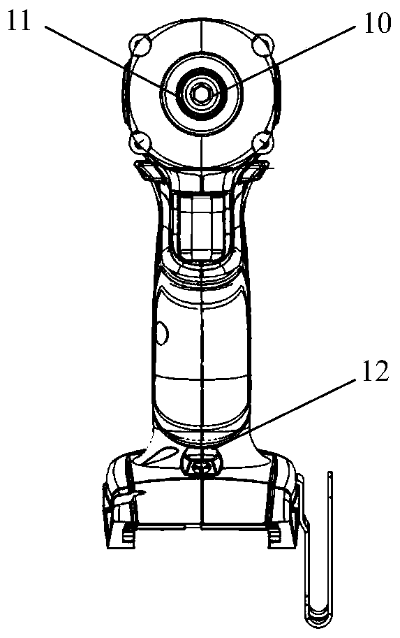
[0046] An electric wrench, comprising a single-chip microcomputer device 2, a switch 3, a power supply device 4, a rear part 5, a machine column 6, a front part 7, a handshake device 8, a motor 9, a wrench shaft 10, a flyweight body 11 and a time setting module 12. The front part 7 and the rear part 5 form the casing part of the motor, and the casing part of the motor, the main body 1 and the power supply device 4 together form an electric wrench, wherein the front part 7 is connected with the machine column 6, and the machine A switch 3 is connected to the front end of the junction between the front part 7 and the machine column 6 , and a handshake device 8 is connected to the lower rear end of the machine column 6 . On main body 1, be provided with single-chip microcomputer device, this single-chip microcomputer device comprises a single-chip microcomputer equipment 2 and time setting module 12, single-chip microcomputer equipment 2 is positioned between power supply unit 4 a...

Embodiment 2

[0048] An electric wrench, which consists of a main body 1 (comprising a single-chip microcomputer device 2, a switch 3, a machine column 6, a handshake device 8 and a motor 9), a power supply device 4, a rear part 5, a front part 7, a wrench shaft 10, a flying The hammer body 11 and the time setting module 12, the front part 7 and the rear part 5 form the casing part of the motor, and the casing part of the motor, the main body 1 and the power supply unit 4 form an electric wrench together, wherein the front part 7 Connected with the machine column 6, the front end of the junction between the front part 7 and the machine column 6 is connected with a switch 3, and the lower rear end of the machine column 6 is connected with a handshake device 8; the trigger shaft 10 is adjacent to the flyweight body 11 and is located at within the casing. On main body 1, be provided with single-chip microcomputer device, this single-chip microcomputer device comprises a single-chip microcomput...


PUM


Abstract

The invention provides a novel electric spanner with adjustable striking force. The electric spanner comprises a power source device, a machine case portion, a main machine body, a switch, a pull shaft, a flyweight body and a motor. The main machine body is provided with a single-chip microcomputer device comprising single-chip microcomputer equipment and a time setting module. The single-chip microcomputer equipment is connected with the switch and the time setting module. When the value of the current of the motor is any value between 10A-50A, a single-chip microcomputer adjusts the flyweight body, so that the flyweight body begins striking parts. The time setting module can be used for setting the striking time of the flyweight body. The invention provides the electric spanner, and an application method and the application thereof. According to the electric spanner, by means of the single-chip microcomputer device, the striking force of the flyweight body of the electric spanner is controllable, the time for striking is controllable, the screwed parts are stable and firm, and therefore the electric spanner and the single-chip microcomputer equipment are lasting in durability.

Description

technical field [0001] The invention relates to an electric wrench, which is suitable for disassembling bolts, nuts and the like in the manufacturing and repairing industry. Background technique [0002] Electric wrench is a wrench powered by power supply or battery. It is a tool for tightening bolts; it is mainly divided into impact wrench, torsional shear wrench, constant torque wrench, angle wrench, angle wrench, hydraulic wrench, torque wrench, rechargeable wrench. The electric wrench is mainly used in the steel structure installation industry. It is specially used to install high-strength bolts in steel structures. High-strength bolts are used to connect the joints of steel structures, usually in the form of bolt groups; high-strength bolts can be divided into torsional shear type and large hexagonal type. Two types, national standard torsional shear type high-strength bolts are M16, M20, M22, M24 four types, non-national standard M27, M30 two types; national standard ...

Claims


Application Information

Patent Timeline
IPC IPC(8): B25B21/00
CPCB25B21/02
Inventor 单志锋
Owner 浙江立邦电器有限公司
Why Eureka
Try Eureka