
Finish forging die for forging aluminum alloy wheel

A technology of aluminum alloy and wheels, which is applied in the direction of manufacturing tools, metal processing equipment, forging/pressing/hammer devices, etc., can solve the problems of poor mechanical properties, difficult demoulding, workpiece damage, etc., so as to solve the problem of uneven iron material and guarantee Mechanical properties, the effect of facilitating wear parts

Inactive Publication Date: 2014-04-30
连云港宝石精密重工科技有限公司
View PDF8 Cites 7 Cited by
  • Summary
  • Abstract
  • Description
  • Claims
  • Application Information

AI Technical Summary

Problems solved by technology

Forged aluminum alloy wheels have been widely used in passenger cars, trailers, oil tank trucks, engineering vehicles, school buses and other vehicles, but the forging dies for forging aluminum alloy wheels are still in the growth stage in China, and are now integrated with traditional final forging dies. It is inconvenient to clean the cavity and maintain, and the problems of uneven material cutting and insufficient mold closure often occur during material cutting; the existing traditional final forging mold opening process is first to open the mold and then demould, so that the workpiece is prone to collision with the mold , causing damage to the workpiece
At the same time, the waste of traditional final forging dies is serious, it is not easy to demould, it is inconvenient to disassemble and replace wear parts, the forged products are short of materials, have poor mechanical properties and low product qualification rate

Method used


Image

  • Finish forging die for forging aluminum alloy wheel

Examples


Embodiment Construction

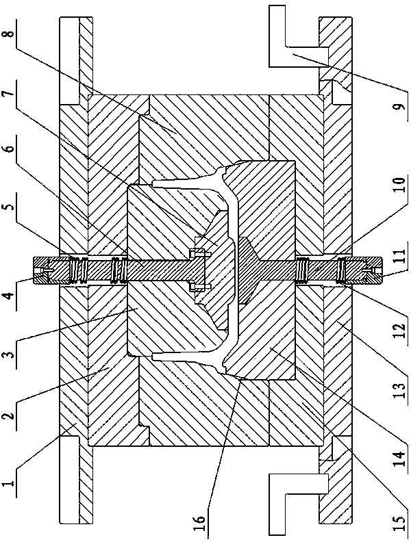
[0010] A final forging die for forging aluminum alloy wheels, comprising an upper template 1 and a lower template 13, a lower mold 14 is fixed above the lower template 13 through a lower supporting plate 15, and an upper mold is fixed below the upper template 1 through an upper supporting plate 2 Die, the upper mold includes an upper mold core 3 facing the lower mold 14, the upper mold core 3 is covered with an upper mold cover 8 fixedly connected with the upper supporting plate 2, and the lower part of the upper mold cover 8 is sleeved outside the lower mold 14 , the bottom of the upper die cover 8 is provided with a notch protrusion engaged with the lower supporting plate 15, forming a closed forging cavity between the upper die core 3, the upper die cover 8 and the lower die 14; There is a circle of gaps on the outer wall of the upper part, and a flash reserved cavity 16 is formed between the inner wall of the upper mold sleeve and the gap of the lower mold. A lower ejector ...


PUM


Abstract

A finish forging die for forging an aluminum alloy wheel comprises an upper die plate and a lower die plate. A lower die is fixed above the lower die plate. An upper die is fixed below the upper die plate. The upper die comprises an upper die core, and the upper die core is sleeved with an upper die sleeve. A circle of notch is formed in the outer wall of the upper portion of the lower die. A flash reserving cavity is formed between the inner wall of the upper die sleeve and the notch of the lower die. A lower ejector rod is arranged at the center of the lower die. An upper ejector rod is arranged at the center of the upper die core. The problems that iron materials are not even and a die is not in place when the quantity of materials is large are solved through the flash reserving cavity formed between the inner wall of the upper die sleeve and the notch of the lower die; a workpiece can be pressed on a lower die core through the upper ejector rod arranged right at the center of the upper die core so that the die can be released, and damage caused when the workpiece collides with the die is avoided; the workpiece is ejected out of the lower die core through the lower ejector rod arranged right at the center of the lower die core, and therefore the forging process is achieved; compared with a traditional die, the finish forging die has the advantages of being free of die holding, easy to release and not prone to strain.

Description

technical field [0001] The invention relates to a die, in particular to a final forging die for forging an aluminum alloy wheel. Background technique [0002] The forging method of aluminum alloy wheels began in China at the beginning of this century, which is a new technology. Forged aluminum alloy wheels have been widely used in passenger cars, trailers, oil tank trucks, engineering vehicles, school buses and other vehicles, but the forging dies for forging aluminum alloy wheels are still in the growth stage in China, and are now integrated with traditional final forging dies. It is inconvenient to clean the cavity and maintain, and the problems of uneven material cutting and insufficient mold closure often occur during material cutting; the existing traditional final forging mold opening process is first to open the mold and then demould, so that the workpiece is prone to collision with the mold , causing damage to the workpiece. At the same time, the current traditiona...

Claims


Application Information

Patent Timeline
IPC IPC(8): B21J13/02B21J13/14
Inventor 胡磊
Owner 连云港宝石精密重工科技有限公司
Learn More