A high energy ignition coil

An ignition coil, high-energy technology, applied in engine ignition, ignition controller, spark ignition controller, etc., can solve the problems of large ignition energy and inability to provide, and achieve the effect of improving energy conversion efficiency

Active Publication Date: 2018-01-12
UNITED AUTOMOTIVE ELECTRONICS SYST
View PDF9 Cites 1 Cited by
  • Summary
  • Abstract
  • Description
  • Claims
  • Application Information

AI Technical Summary

Problems solved by technology

Existing ignition coils cannot provide such a large ignition energy

Method used


Image

  • A high energy ignition coil
  • A high energy ignition coil
  • A high energy ignition coil

Examples


Embodiment Construction

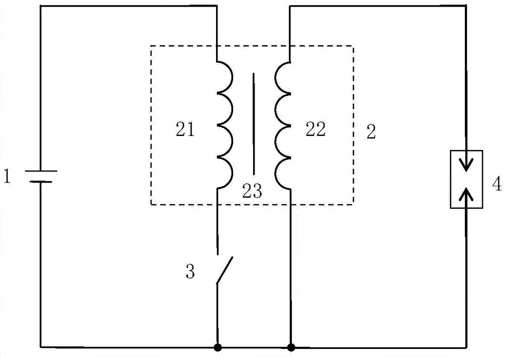
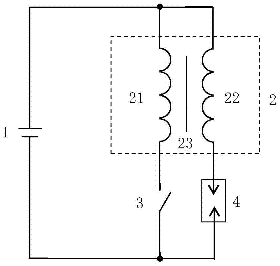
[0016] see Figure 1a and Figure 1b , the ignition energy value of the ignition coil Wherein T is the discharge time of the secondary coil 22 on the secondary coil circuit, u ISK-OUT is the ground pressure drop value of the end of the secondary coil 22 connected to the spark plug 4, i OUT is the value of the current through the secondary coil (i.e. the secondary current).

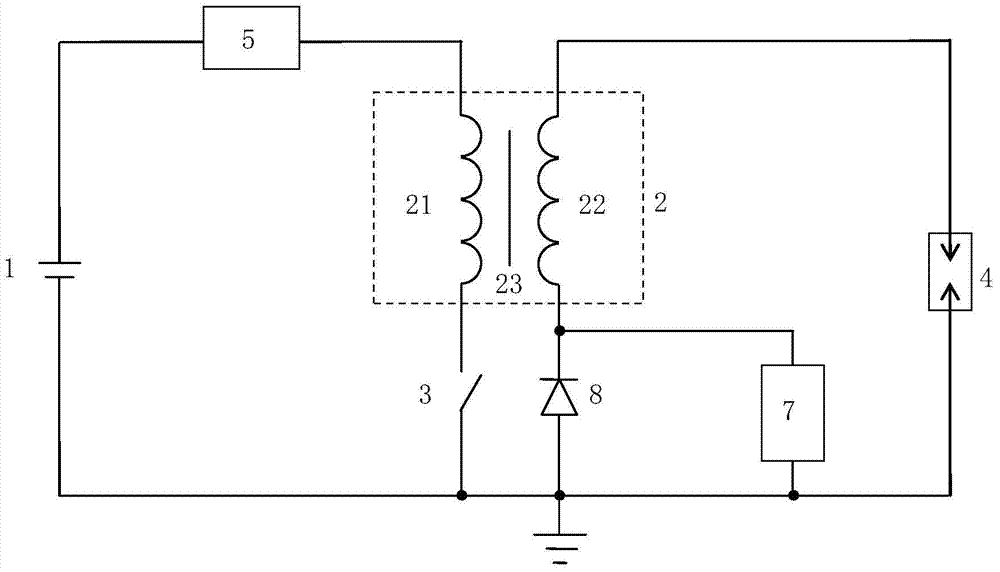
[0017] In the high-energy ignition coil of the present application, the discharge of the secondary coil 22 on the secondary coil circuit can be divided into two stages: the first stage is that the energy of the primary coil 21 is coupled to the secondary coil 22 to make the spark plug 4 conduct. The first stage is from time 0 to time T1 with a length of T1. The second stage is that the energy provided by the current maintaining device 7 turns on the spark plug 4 , and the second stage is from the time T1 to the time T1+T, and the length is T2. T=T1+T2. Therefore, the ignition energy value of the high...


PUM

PropertyMeasurementUnit
electric energyaaaaaaaaaa

Abstract

The application discloses a high-energy ignition coil, the primary coil and the secondary coil are both wound on the iron core, and the three constitute a transformer. There is a switch controlled by the ECU on the primary coil circuit. One electrode of the spark plug is connected to one end of the secondary coil, and the other electrode of the spark plug is grounded. The vehicle-mounted power supply supplies power to the primary coil through a DC booster, and the DC booster boosts the DC voltage output by the vehicle-mounted power supply and then outputs it. The other end of the secondary coil is connected either to a DC booster or to ground through a reverse connected diode. The current maintaining device is connected in parallel with the series branch of the secondary coil and the spark plug, and works to maintain the continuous conduction of the spark plug after the spark plug is turned on. The ignition coil of the present application can adjust the conduction time of the spark plug arbitrarily, so that the ignition energy can be increased; a higher voltage is also used to connect the primary coil, thereby improving the energy conversion efficiency.

Description

technical field [0001] The present application relates to an ignition coil for an internal combustion engine vehicle. Background technique [0002] see Figure 1a , which is an existing ignition coil. The vehicle power supply 1 is usually a low-voltage DC power supply with a rated voltage between 8V and 16V, which is used to supply power to the primary coil 21 . The vehicle power supply 1 and the primary coil 2 constitute a primary coil circuit, on which a switch 3 controlled by an ECU (Electronic Control Unit) is provided. One end of the secondary coil 22 is grounded, the other end is connected to one electrode of the spark plug 4, and the other electrode of the spark plug 4 is grounded. The secondary coil 22 and the spark plug 4 form a secondary coil circuit. Both the primary coil 21 and the secondary coil 22 are wound on an iron core 23 , and these three constitute a transformer 2 . [0003] Figure 1a The ignition coil shown can also be modified as Figure 1b In thi...

Claims


Application Information

Patent Timeline
Patent Type & Authority Patents(China)
IPC IPC(8): H01F38/12H01F27/40
CPCH01F38/12H01T15/00F02P3/0407F02P3/05F02P9/002F02P9/007F02P15/10F02P3/00H01T13/00F02P3/0807F02P3/0876
Inventor 茅一春孙晓庆李毓强程捷
Owner UNITED AUTOMOTIVE ELECTRONICS SYST
Why Eureka
Try Eureka