Synchronous different speed transmission wheel

A technology of synchronous different speeds and transmission wheels, applied in the direction of belts/chains/gears, portable lifting devices, elements with teeth, etc.

Inactive Publication Date: 2014-04-23
柳州力通汽车科技有限公司
View PDF5 Cites 0 Cited by
  • Summary
  • Abstract
  • Description
  • Claims
  • Application Information

AI Technical Summary

Problems solved by technology

[0002] Existing drive wheels generally can only be connected to one drive belt, or the teeth on the top of the drive wheel are parallel

Method used


Image

  • Synchronous different speed transmission wheel

Examples


Embodiment Construction

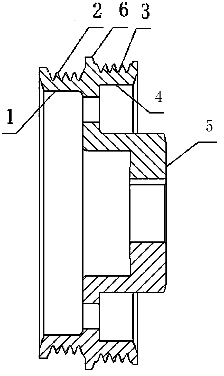
[0013] Such as figure 1 As shown, the outer wall of the synchronous differential transmission wheel is stepped, the large diameter end 4 and the small diameter end 1, the large diameter end 4 and the small diameter end 1 have uniformly distributed conical teeth 2 and 3, the large diameter end 4 and the small diameter end 1 There are raised spacer ribs 6 between them, and the diameter formed by the conical tooth tops at the large diameter end is greater than the diameter formed by the small diameter end conical tooth tops.

[0014] There is a protrusion 5 in the middle part of the transmission wheel disc.

[0015] The protrusion 5 is in the shape of a shell, and the center of the shell is provided with a central hole, and the wall of the hole is provided with a keyway for connecting the transmission shaft.

[0016] The inner diameter of the large-diameter end 4 is larger than the diameter of the small-diameter end 1 .

[0017] The protrusion faces the large diameter end 4 , a...


PUM


Abstract

The invention provides a synchronous different speed transmission wheel. The outer wall of the transmission wheel is stepped, conical teeth are uniformly distributed outside a large-diameter end and a small-diameter end, projecting partition edges are arranged between the large-diameter end and the small-diameter end, and diameters formed at tooth tops of the conical teeth of the large-diameter end are larger than those formed at tooth tops of the conical teeth of the small-diameter end. The synchronous different speed transmission wheel can be connected with two transmission belts, so that transmission speed is changed.

Description

technical field [0001] The invention relates to a synchronous variable speed transmission wheel, which belongs to the technical field of automobile machinery. Background technique [0002] The existing driving wheel generally can only be connected with one driving belt, or the teeth on the top of the driving wheel are parallel. Contents of the invention [0003] The invention provides a synchronous variable-speed transmission wheel, which can connect two transmission belts to change the transmission speed. [0004] In order to solve the above technical problems, the present invention provides the following technical solutions: a synchronous differential transmission wheel, the outer wall of the transmission wheel is stepped, the large diameter end and the small diameter end, and the large diameter end and the small diameter end have uniformly distributed taper The tooth has a raised spacer between the large diameter end and the small diameter end, and the diameter formed ...

Claims


Application Information

Patent Timeline
Patent Type & Authority Applications(China)
IPC IPC(8): F16H55/36
CPCF16H55/36
Inventor 李峰
Owner 柳州力通汽车科技有限公司
Why Eureka
Try Eureka