Auxiliary positioning device

An auxiliary positioning and leaning technology, applied in the direction of positioning device, clamping, support, etc., can solve problems such as difficulty in meeting process requirements, damage to tooling, cumulative errors, etc., achieve simple and reasonable structure, improve machining accuracy, and eliminate gap errors. Effect

Active Publication Date: 2016-04-13
GUANGXI YUCHAI MASCH CO LTD
View PDF8 Cites 0 Cited by
  • Summary
  • Abstract
  • Description
  • Claims
  • Application Information

AI Technical Summary

Problems solved by technology

If the gap is small, it is easy to insert the product process hole when installing the product, which will affect the use of the next process, and when disassembling the product, it is easy to pull out the positioning pin and damage the tooling; Inaccurate positioning is prone to cumulative errors and affects product accuracy
For example, "two pins on one side" is used to locate the positioning pin with a short cylindrical manufacturing tolerance of φ20 (0~-0.04), and the tolerance of the process hole is φ20 (+0.04~+0.02). In this way, the gap between the two positioning pins and the process hole has an error of 0.08, and the process requires The distance tolerance from the processing surface to the process hole is ±0.05, and due to the verticality and flatness error of the processing surface, it is difficult to meet the process requirements. Moreover, according to the product requirements, the distance tolerance from the processing surface to the process hole is ±0.04, and there are direction requirements, which is even more difficult. Meet the requirements

Method used


Image

  • Auxiliary positioning device

Examples


Embodiment Construction

[0017] A specific embodiment of the present invention will be described in detail below in conjunction with the accompanying drawings, but it should be understood that the protection scope of the present invention is not limited by the specific embodiment. It should be understood that the "upper", "lower", "left", "right", "front" and "reverse" mentioned in the following embodiments of the present invention are all based on the directions shown in the figures, These words used to limit the direction are only for convenience of description, and do not mean to limit the specific technical solution of the present invention.

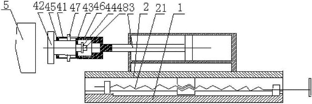
[0018] The structure of the auxiliary positioning device of the present invention is simple and reasonable. By pushing the part to be processed against the cylindrical generatrix on the side of the positioning pin, and then clamping the part by the clamping device, the two positioning pins and the process hole can be eliminated under normal tolerance matching...


PUM


Abstract

The invention discloses an auxiliary location device which comprises a base fixed on a machine tool sliding table, a movable seat movably installed on the base through a screw pair, a pushing oil cylinder installed on the movable seat and an abutting assembly. One end of the abutting assembly is fixed with a piston rod of the pushing oil cylinder, and an abutting head of a part to be machined is arranged at the other end of the abutting assembly. The auxiliary location device is simple and reasonable in structure, a part to be machined abuts against a cylinder bus on one side of the location pin and is clamped through a clamping device, clearance errors between two location pins and process holes are removed under the normal tolerance matching requirement, and part machining accuracy is improved.

Description

technical field [0001] The invention relates to the field of positioning tooling, in particular to an auxiliary positioning device. Background technique [0002] In mechanical processing, for the processing of box-type parts, the positioning method is usually "two pins on one side". There is a certain gap between the two positioning pins and the process hole of the product, so that the product can be installed in place on the tooling. If the gap is small, it is easy to insert the product process hole when installing the product, which will affect the use of the next process, and when disassembling the product, it is easy to pull out the positioning pin and damage the tooling; Inaccurate positioning is prone to cumulative errors and affects product accuracy. For example, "two pins on one side" is used to locate the positioning pin with a short cylindrical manufacturing tolerance of φ20 (0~-0.04), and the tolerance of the process hole is φ20 (+0.04~+0.02). In this way, the ga...

Claims


Application Information

Patent Timeline
Patent Type & Authority Patents(China)
IPC IPC(8): B23Q3/18
CPCB23Q3/18
Inventor 胡维民卢明李柳华莫贻镇杨育覃金夏
Owner GUANGXI YUCHAI MASCH CO LTD
Why Eureka
Try Eureka