
Flat cross-connector for spinal fixation

A flat fixator technology, applied in fixers, internal fixators, internal bone synthesis, etc., can solve the problems of increasing the difficulty of surgical suturing, strong foreign body sensation on the patient's back, etc., to achieve convenient and quick installation, reduce suturing difficulty, and improve The effect on success rate

Active Publication Date: 2014-04-23
SHANDONG HANGWEI ORTHOPEDICS MEDICAL INSTR
View PDF5 Cites 1 Cited by
  • Summary
  • Abstract
  • Description
  • Claims
  • Application Information

AI Technical Summary

Problems solved by technology

To sum up, in the current horizontal connectors, the locking bolts are located above the horizontal connecting rod and the overall height is high. Such a structure increases the difficulty of suturing and makes the patient feel a strong foreign body on the back.

Method used


Image

  • Flat cross-connector for spinal fixation
  • Flat cross-connector for spinal fixation
  • Flat cross-connector for spinal fixation

Examples


Embodiment approach

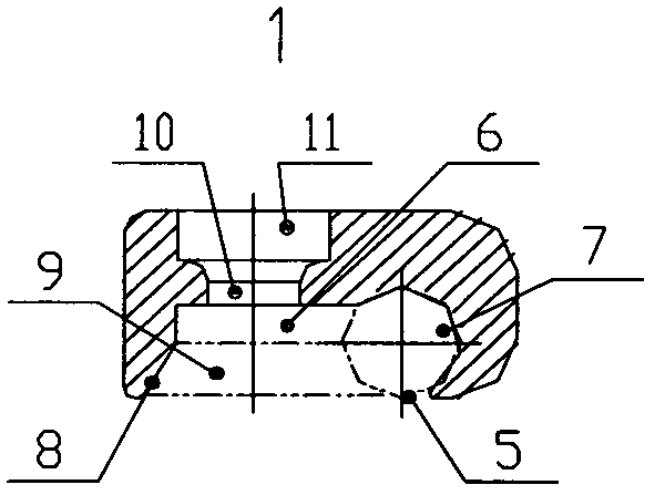
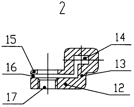
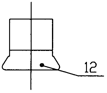
[0017] Figure 1 to Figure 6 It shows the embodiment of the flat horizontal connector for spinal fixation of the present invention, which includes two hooks 1, two locking bodies 2, two locking screws 3, one horizontal connecting rod 4 and the nail of the spinal fixator There are 5 sticks.

[0018] figure 1 Shown in the embodiment, the structure of the component hook 1 of the flat horizontal connector for spinal fixation, the bottom of the hook 1 is provided with a through groove 6, and one side of the groove 6 is provided with an opening facing inward. The arc groove 7 is used to hook the nail rod 5 of the spinal fixator in the horizontal direction, and the nail rod 5 is in the figure 1 Shown by double-dotted lines, the other side of the groove 6 is provided with an inclined surface 8, the inclined surface 8 and the surface of the nail bar 5 form a downwardly open trapezoidal groove 9, and the trapezoidal groove 9 is in the figure 1 Shown by double dotted lines in the figu...


PUM


Abstract

The invention discloses a flat cross-connector for spinal fixation. The flat cross-connector comprises two hooks 1, two lockers 2, two lock screws 3 and a cross connecting rod 4. The hooks are provided with grooves and lock screw holes; the lockers are provided with cross connecting rod slots, trapezoidal parts and lock thread holes. During use, two nails 5 of a spinal fixator are fixed at first, the two lockers are respectively arranged on the inner sides of the two nails, the cross connecting rod is then inserted into the two cross connecting rod slots, the two nails are hooked by the two hooks respectively and then fastened in the trapezoidal parts of the lockers, the lock screw holes and the lock thread holes are adjusted to be coaxial, the two lock screws are respectively screwed into the two lock thread holes, the two hooks are pulled to the two lockers until the two nails are locked, and the cross connecting rod slots are enabled to deform to lock the cross connecting rod. In application of the flat cross-connector for spinal fixation, position of lock screws of conventional cross-connectors is changed, height of the cross-connector is reduced, surgical suture difficulty is lowered, and foreign body sensation to patients after surgery is weakened.

Description

technical field [0001] The invention relates to the field of orthopedic medical instruments. Background technique [0002] At present, in the spinal column injury operation, a spinal fixator plus a transverse connector is commonly used to fix the spine. The spinal fixator includes a pedicle screw and a screw rod, and the transverse connector includes two hooks, two locking Bolts and a horizontal connecting rod. A groove is provided below the hook to hook the nail bar. The hook is provided with a through horizontal connecting rod groove on the nail bar and in a direction perpendicular to the nail bar. The connecting rod is inserted into the connecting rod groove to connect the two hooks, the locking bolt is arranged above the connecting rod groove of the hook, and the connecting rod and the connecting rod are connected by force from top to bottom. Nail bar locked. Invention patent CN201110208678.5 discloses a horizontal connector for spinal fixation, which includes two clam...

Claims


Application Information

Patent Timeline
IPC IPC(8): A61B17/70
CPCA61B17/7049
Inventor 孙德修
Owner SHANDONG HANGWEI ORTHOPEDICS MEDICAL INSTR
Learn More