
Frying machine

A frying machine and oil tank technology, which is applied in the direction of oil/fat baking, etc., can solve the problems of large temperature error, poor transmission effect, and short life of AC contactors, so as to improve the transmission effect and realize large-scale intensive frying Effect of processing and reducing labor cost operation

Active Publication Date: 2014-04-23
PENGLAI JINGLU FISHERY
View PDF10 Cites 15 Cited by
  • Summary
  • Abstract
  • Description
  • Claims
  • Application Information

AI Technical Summary

Problems solved by technology

However, there are also the following disadvantages or deficiencies at the same time: the common temperature controller is used on the heating pipe, if the switch is switched on and off too frequently, the life of the AC contactor will be very short, and the temperature error is relatively large, which is easy to cause the phenomenon of frying; During the frying process, the oil cake starts to be placed on the output mesh belt, which will stick to the pan or the oil cake will be deformed on the uniform output mesh belt, which will directly cause the cleaning problem of the frying tank and the shape of the oil cake will be damaged; and during the frying process, Soaking in the frying tank will absorb a lot of oil, which will take away the oil in the subsequent transmission process and waste oil; during the transmission process, the phenomenon of sticking to the pan will also lead to poor transmission effect

Method used


Image

  • Frying machine
  • Frying machine

Examples


Embodiment Construction

[0020] The principles and features of the present invention are described below in conjunction with the accompanying drawings, and the examples given are only used to explain the present invention, and are not intended to limit the scope of the present invention.

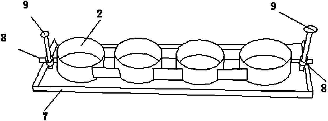
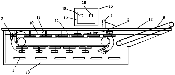
[0021] Such as figure 1 As shown, it is a schematic structural view of a frying machine, including a main frame 12, a frying tank 13, and a transmission chain 11. A frying tank 13 is installed on the main frame 12, and the bottom of the frying tank 13 is installed There is a heating pipe 1; a transmission chain 10 is installed on the side of the main frame 12 close to the frying tank 13, a partition 7 is installed on the transmission chain 11, and a cylinder 2 is installed on the partition 7; A hot oil tank 3 is installed on the top bracket of the main frame 12, and a power distribution box 14 is fixed on the outer surface of the hot oil tank 3, and a thyristor 15 and a frequency converter 16 are respectively instal...


PUM


Abstract

The invention relates to the frying machinery field and specifically relates to a frying machine. The frying machine comprises a main frame, a frying tank and a conveying chain. The frying machine is characterized in that the frying tank is mounted on the main frame and a heating tube is mounted at the bottom of the frying tank; the conveying chain is mounted at a side close to the frying tank inside the main frame, a separator is mounted on the conveying chain and a cylinder is mounted on the separator; a hot oil tank is mounted on the top support of the main frame, a power distribution box is fixed on the outer surface of the hot oil tank, a thyristor and a frequency converter are mounted in the power distribution box, respectively, the thyristor is connected with the heating tube, and the frequency converter is connected with the tachometer of the conveying chain; an oil injection tube is mounted at a side close to the outer surface of the hot oil tank, and a transmission chain is mounted at a side close to the conveying chain adjacent to the oil injection tube. The factor of poor conveying effect of the previous frying machine is overcome; the frying machine is not only convenient to operate and capable of realizing large-scale frying process, and also capable of saving oil and non-sticky to pan; the fried cakes are regular and beautiful in appearance.

Description

technical field [0001] The invention relates to the field of frying machinery, specifically, a frying machine. Background technique [0002] In food processing technology, people often use edible oil to fry all kinds of food at high temperature. Because fried food is fragrant and crispy, it is favored by consumers and has occupied a large and important share in the consumer market. It has gradually become the main food in the market. Therefore, many companies have tried their best to process various fried foods and push them to the market. [0003] Chinese patent 201220532923.8 discloses a continuous frying machine, the structure of which includes a frying tank, the bottom of which is fixed with a heating pipe, and the frying tank includes an inlet port and an outlet port, and the food to be fried starts from the inlet port. Put it in, and the fried finished product is transported out from the outlet end. A transmission plate and a transmission motor are installed on the en...

Claims


Application Information

Patent Timeline
IPC IPC(8): A21B5/08
Inventor 牟伟丽孙大鹏张道旭李建利
Owner PENGLAI JINGLU FISHERY
Learn More