
A self-regulating nozzle type inflow control device

A technology of inflow control and nozzle, which is applied in the direction of production fluid, wellbore/well parts, earthwork drilling and production, etc. It can solve the problems of large resistance, time-consuming and labor-intensive, and small resistance, so as to improve oil well production, uniform inflow profile, reduce coning effect

Inactive Publication Date: 2016-01-20
NORTHEAST GASOLINEEUM UNIV
View PDF6 Cites 0 Cited by
  • Summary
  • Abstract
  • Description
  • Claims
  • Application Information

AI Technical Summary

Problems solved by technology

[0008] However, once the nozzle-type ICD is lowered into the oil well, the length of the nozzle cannot be adjusted, and this usually makes its resistance too high at low flow rates and too small at high flow rates, making it difficult to ensure a sufficiently uniform inflow profile
In addition, when multi-stage ICDs are completed, due to the different reservoir physical properties of different intervals in heterogeneous formations, the required FRR is different. According to the information measured during drilling, it is necessary to check each nozzle before running into the oil well. Optimizing the structural parameters of the ICD-type ICD so that the FRR generated by it adapts to the reservoir physical properties of the interval and ensures that the inflow profile is sufficiently uniform, however, this is usually time-consuming and labor-intensive

Method used


Image

  • A self-regulating nozzle type inflow control device
  • A self-regulating nozzle type inflow control device
  • A self-regulating nozzle type inflow control device

Examples


Embodiment Construction

[0024] Below in conjunction with accompanying drawing, content of the invention will be further described:

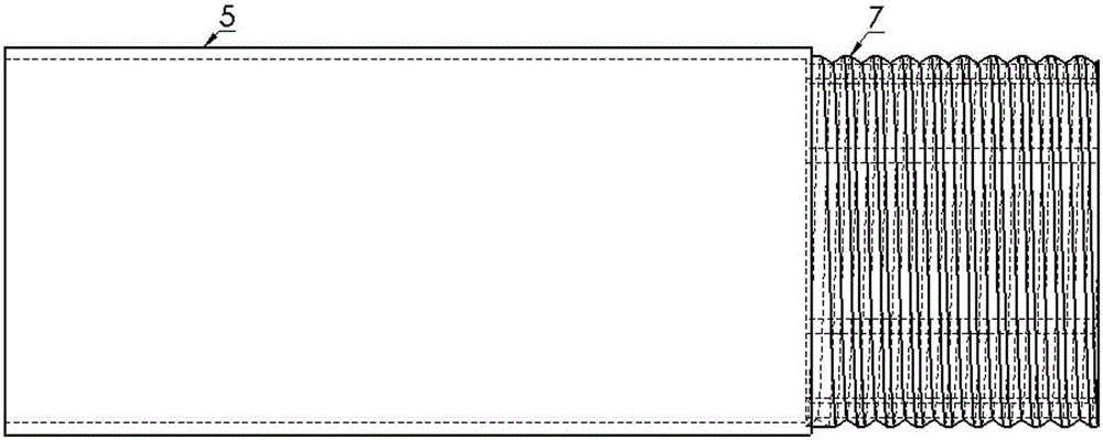
[0025] refer to Figure 1-Figure 5 As shown, the self-regulating nozzle type inflow control device includes a base pipe 1, a jacket and a throttle part 2. The base pipe 1 is connected to the connected oil pipe through the end threaded section 3, and the inner diameter is the same as that of the oil pipe. The base pipe 1 There are holes around the area corresponding to the spring 4 in the throttling part 2 as a passage for the fluid to flow into the base pipe 1. The jacket is divided into an upper jacket 5 and a lower jacket 6, which are connected by a middle thread 7. The upper jacket 5 is divided into Two parts with different inner diameters, the inner surface of the end with the larger inner diameter forms an annulus with the outer surface of the base pipe, which serves as a channel for fluid to flow from the oil jacket annulus to the nozzle, and the part with a small...


PUM


Abstract

An automatic flow adjusting spray pipe type inflow control device comprises a base pipe, an upper sleeve, a lower sleeve, a movable spray pipe and a spring, wherein the base pipe, the upper sleeve, the lower sleeve, the movable spray pipe and the spring are connected. According to the device, the grade of flow resistance can be adjusted automatically according to the rate of flow, influences of the end effect and reservoir anisotropy are counteracted, inflow section is even along a horizontal wellbore, air water coning is reduced, and the yield of an oil well is increased.

Description

technical field [0001] The invention relates to a device for improving the effect of oil field development, in particular to a self-regulating flow nozzle type inflow control device. Background technique [0002] In a long horizontal well, due to the existence of the flow pressure drop in the horizontal wellbore, the production pressure difference at different wellbore locations is different, resulting in the production at the heel of the well is usually much higher than that at the toe, and the resulting uneven production profile may cause wellbore heeling. Premature water / air at tip. Once coning occurs, well production is significantly reduced due to restricted flow at the toe. In order to eliminate this unbalanced phenomenon, commonly used methods include staged perforation, variable density perforation completion, central pipe completion, etc. However, these methods have limited ability to control the inflow profile, and it is difficult to ensure that the production pr...

Claims


Application Information

Patent Timeline
Patent Type & Authority Patents(China)
IPC IPC(8): E21B43/12
Inventor 魏建光赵法军李江涛曾泉树刘达京陈曦
Owner NORTHEAST GASOLINEEUM UNIV
Learn More