
A laser shock treatment method and device for a porous plate

A laser shock and processing device technology, applied in the field of metal processing, can solve the problems of difficulty in meeting the wear resistance requirements of pellet machine template, difficulty in achieving satisfactory impact effect, laser energy dispersion, etc. good impact effect

Inactive Publication Date: 2015-11-18
JIANGSU UNIV
View PDF5 Cites 2 Cited by
  • Summary
  • Abstract
  • Description
  • Claims
  • Application Information

AI Technical Summary

Problems solved by technology

[0004] The existing laser shock strengthening treatment technology uses solid absorbing layer materials (such as black paint coating), which can only treat the outer surface of the workpiece that can be irradiated by the laser beam. For the shock treatment of the inner hole wall, the workpiece must be rotated by a certain angle or Rotate the laser head at a certain angle so that the laser beam can irradiate the inner hole wall. At this time, the laser beam is not perpendicular to the surface to be processed, the laser energy is dispersed, and the impact effect is poor, so it is difficult to achieve a satisfactory impact effect.
[0005] If the liquid absorbing layer material is used in the existing laser shock strengthening treatment technology, because the shock wave attenuates quickly in the liquid absorbing layer material, the shock effect is relatively poor for the shock treatment of the inner hole wall that requires high impact strength, and it is difficult to reach the particle size. Wear resistance requirements for parts such as machine formwork

Method used


Image

  • A laser shock treatment method and device for a porous plate
  • A laser shock treatment method and device for a porous plate
  • A laser shock treatment method and device for a porous plate

Examples


Embodiment Construction

[0028] The details and working conditions of the specific device proposed by the present invention will be described in detail below in conjunction with the accompanying drawings.

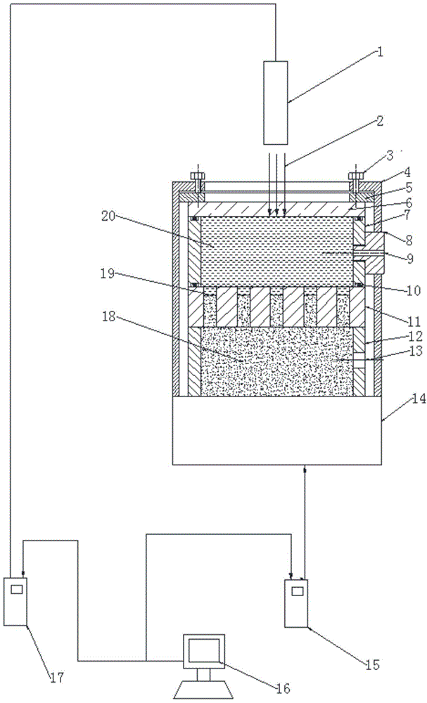
[0029] A kind of perforated plate laser shock treatment device, such as figure 1 As shown, it includes laser generator 1, compression screw 3, fixture 4, pressure plate 5, glass 6, water tank 7, water inlet pipe 8, sealing ring 10, workpiece 11, lower tube 12, workbench 14, workbench control device 15 , a computer 16, a laser generator control device 17, a viscoelastic fluid 18, and a transparent liquid 20; After the elastic fluid 18 and the viscoelastic fluid 18 pass through the holes on the porous plate workpiece 11 that need impact treatment, the upper surface thereof is slightly lower than the upper surface of the porous plate workpiece 11 or is flush with the upper surface of the workpiece 11, and the porous plate workpiece 11 is placed On the lower cylinder 12, the holes that need impact tre...


PUM


Abstract

The invention relates to a laser shock treatment method of a porous plate. By using a transparent liquid and glass as a composite restraint layer and a viscoelastic fluid material as an absorption layer, the position of the viscoelastic fluid in pores is changed through the pressure of the transparent liquid, so that all the pore walls are treated. The device is composed of a laser generator, a compression screw, a clamp, a pressure plate, glass, a water tank, an upper cylinder, a water inlet pipe, a seal ring, a workpiece, a lower cylinder, a worktable, a worktable control unit. a computer, a laser generator control unit, a viscoelastic fluid and a transparent liquid. When the porous plate is subjected to laser shock treatment, since the laser penetration depth of the viscoelastic fluid is small, the energy is concentrated on the upper surface of the viscoelastic fluid, and thus, the shock strength is obviously enhanced as compared with the liquid absorption layer. Besides, the flowability of the viscoelastic fluid is poor, and the attenuation of shock waves penetrating through the viscoelastic fluid is small, so the glass is utilized to restrict the splash of the transparent liquid, thereby further enhancing the laser shock effect.

Description

Technical field: [0001] The invention relates to the field of metal processing, in particular to a treatment method and device for shocking the hole wall of a porous plate based on laser shock wave technology. Background technique: [0002] In the industrial field, there are many occasions that need to use porous plates, such as templates for straw pellet machines, etc. Such workpieces often have high requirements on the wear resistance of the hole walls, and the strengthening of the hole walls of commonly used porous plates generally uses methods such as carburizing and quenching. , due to the heat treatment after the perforated plate is punched, the deformation is relatively large, and follow-up treatment is often required. [0003] Laser shock treatment has the advantages of good controllability of laser parameters and high laser shock intensity, so it has broad application prospects. Laser shock treatment is to irradiate the surface of the workpiece with a strong laser ...

Claims


Application Information

Patent Timeline
Patent Type & Authority Patents(China)
IPC IPC(8): C21D10/00
Inventor 顾永玉张永冯爱新叶云霞肖爱民
Owner JIANGSU UNIV
Learn More