Infrared radiation temperature measurement calibration device and calibration method for chemical vapor deposition equipment

A chemical vapor deposition and infrared radiation technology, which is applied in the field of infrared radiation temperature measurement and calibration devices, can solve the problems of inconvenient operation, inaccurate relative temperature readings of the tester, and inability to meet the requirements of measurement accuracy, so as to eliminate the influence of emissivity. Temperature, relative temperature accurate effect

Active Publication Date: 2016-04-13
甘志银
View PDF8 Cites 0 Cited by
  • Summary
  • Abstract
  • Description
  • Claims
  • Application Information

AI Technical Summary

Problems solved by technology

[0004] Although the two methods disclosed above can improve the accuracy of single-point temperature measurement to a certain extent, they still cannot meet the requirements of relative temperature measurement accuracy for multi-point temperature monitoring in metal organic chemical vapor deposition equipment in practical applications, and It is sometimes inconvenient to operate
Because the infrared radiation capability obtained by measurement is related to the installation position of the tester and the structure of the optical detection port of the radiated light, the material of the optical window, manufacturing, and assembly errors, these errors will lead to the same temperature, and the data read by each test port is different. , that is, the relative temperature readings of each tester are inaccurate, and this inaccurate feedback result will affect the accuracy of the temperature uniformity adjustment of the loading plate

Method used


Image

  • Infrared radiation temperature measurement calibration device and calibration method for chemical vapor deposition equipment

Examples


Embodiment 1

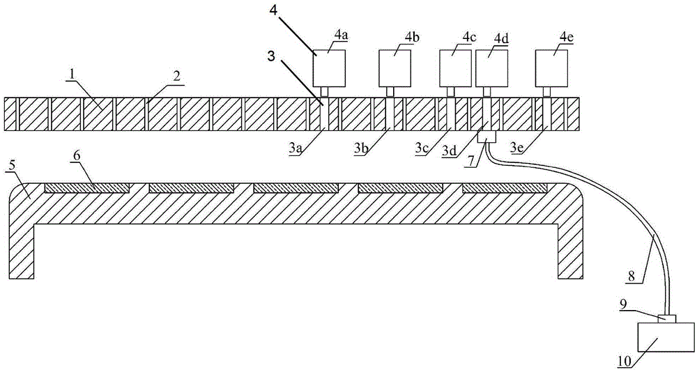
[0019] see figure 1 , The infrared radiation temperature measurement and calibration device of the present invention includes an infrared radiation temperature tester 4, an optical detection hole 3, a black body furnace 10, an optical fiber or a light beam 8, a detection hole end clamp 7 and a black body furnace end clamp 9. The optical detection hole 3 is a through hole that can transmit light. There are five optical detection holes 3 in this implementation, which are respectively arranged in the shower plate 1, and are optical detection hole one 3a, optical detection hole two 3b, and optical detection hole three. 3c, optical detection hole four 3d, optical detection hole five 3e, four infrared radiation temperature testers 4 are also provided: infrared radiation temperature tester one 4a, infrared radiation temperature tester two 4b, infrared radiation temperature tester three 4c, infrared radiation temperature tester 4 4d, infrared radiation temperature tester 5 4e, the fiv...


PUM


Abstract

The invention discloses an infrared radiation temperature measurement calibrating device for chemical vapor deposition equipment, and a calibration method thereof. The optical detection holes capable of light transmission, of the calibrating device are arranged in a spraying disc; infrared radiation temperature testers are arranged to be corresponding to the optical detection holes in the spraying disc; and fibers or light beams are fixed through a black-body furnace end clamp and a detection hole end clamp and are connected between a black-body furnace and the optical detection holes. Through the fibers or the light beams, infrared radiation of the black-body furnace is introduced to the optical detection openings of the spraying disc of the metal organic chemical vapor deposition equipment, and on-line calibration can be performed on the infrared radiation temperature testers above the spraying disc. The advantages are as follows: the structure is simple, temperature differences caused by system errors and assembling factors of an infrared radiation temperature tester system itself can be eliminated, the relative temperature tested by each infrared radiation temperature tester is more accurate, and the uniformity adjustment of the surface temperature of a substrate bearing plate is facilitated, thus the problem of temperature calibration of the metal organic chemical vapor deposition equipment is solved.

Description

technical field [0001] The invention relates to the field of non-contact infrared temperature measurement, in particular to an infrared radiation temperature measurement calibration device and a calibration method for metal organic chemical vapor deposition chemical vapor deposition equipment. Background technique [0002] Chemical vapor deposition technology (MetalOrganicChemicalVaporDeposition, referred to as MOCVD) integrates precision machinery, semiconductor materials, vacuum electronics, fluid mechanics, heat transfer, optics, chemistry, and computer disciplines. It is a highly automated, expensive, and technologically integrated High-end semiconductor materials, optoelectronic special equipment. MOCVD is a non-equilibrium growth technology. Its working mechanism is to transfer the source gas, so that the group III alkyl compound (TMGa, TMIn, TMAl, magnesium dicene, etc.) and the V group hydride (AsH3, PH3, NH3, etc.) A pyrolysis reaction is performed on the substrate...

Claims


Application Information

Patent Timeline
Patent Type & Authority Patents(China)
IPC IPC(8): G01J5/00G01J5/08
Inventor 甘志银胡少林潘建秋蒋小敏植成杨刘玉贵
Owner 甘志银
Why Eureka
Try Eureka