
Ventilation and temperature control system for animal housing

A technology of temperature control system and animal pen, applied in animal houses, applications, animal husbandry, etc., can solve the problems of animal susceptibility, poor resistance, feed consumption, etc., to reduce the incidence rate, implement transformation, change small effect

Inactive Publication Date: 2015-08-19
李学杰
View PDF9 Cites 0 Cited by
  • Summary
  • Abstract
  • Description
  • Claims
  • Application Information

AI Technical Summary

Problems solved by technology

Although this saves the cost of breeding, it still cannot be solved well if it is too hot in summer and too cold in winter.
Later, someone proposed to install forced ventilation equipment on the side wall. Although this can enhance the air flow inside the pen, the gas in the pen septic tank often contains harmful gases. When it is drawn out by the exhaust fan on the side wall , the harmful gas passes through the animal rest area, which is harmful to the animal's health
Moreover, in the hot summer and cold winter, it is impossible to keep the temperature inside the enclosure constant, the ambient temperature is too low, and the internal temperature of the enclosure is low, causing some animals to be unable to resist the low temperature, the consumption of feed does not grow meat, the resistance is poor, and the animal morbidity rate High, seriously affecting the growth and survival of animals
Some people also proposed to install air conditioners in animal pens to ensure a constant temperature inside the pens, but the cost of breeding has been greatly increased, and animals are also prone to "air conditioning disease", which is not good for animal health.

Method used


Image

  • Ventilation and temperature control system for animal housing
  • Ventilation and temperature control system for animal housing
  • Ventilation and temperature control system for animal housing

Examples


Embodiment Construction

[0021] The present invention will be further described below in conjunction with the accompanying drawings, but the protection scope of the present invention is not limited to the following description.

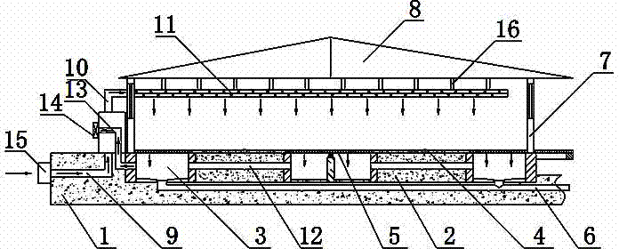
[0022] Such as figure 1 As shown, the ventilation and temperature control system for animal pens includes a base soil 1, a plain soil layer 2 arranged above the base soil 1, a defecation tank 3 arranged between adjacent plain soil layers 2, and a 1 around the side wall 7 and the ceiling 8 installed on the top of the side wall 7, a rest area 4 is arranged above the plain soil layer 2, a dung leakage board 5 is arranged above the defecation tank 3, and the bottom of the defecation tank 3 is connected with a urination Pipe 6, which also includes multiple groups of air intake system, exhaust system and temperature control device 15:

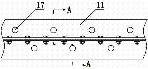
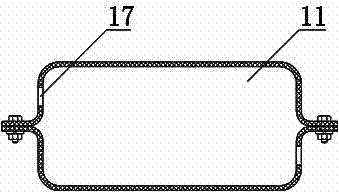
[0023] Such as figure 2 and image 3 As shown, the air inlet system includes an air inlet channel 9, an air inlet pipe 10 and an air outlet pip...


PUM


Abstract

The invention relates to a ventilation and temperature control system for animal housing. The ventilation and temperature control system comprises a plurality groups of air inlet systems, air exhaust systems, and temperature control devices (15), wherein each of the air inlet systems comprises an air inlet channel (9), an air inlet pipe (10) and an air outlet pipe (11); the air outlet port of the air inlet channel (9) is communicated with the air inlet pipe (10), the air inlet pipe (10) stretches in the inner side of a side wall (7) and is communicated with the air outlet pipe (11); each of the air exhaust systems comprises a middle pipe (12), an air exhaust pipe (13) and a fan (14); the middle pipe (12) is arranged in a plain soil layer (2), the air exhaust pipe (13) is communicated with a defecation pool (3) close to the outermost side, and the fan (14) is installed at the air outlet of the air exhaust pipe (13); the temperature control devices are arranged at the air inlets of the air inlet pipes (9). The advantages of the ventilation and temperature control system disclosed by the invention lie in that the morbidity of animals is reduced, the energy consumption is low, and the changes on the original structure of pig housing are few.

Description

technical field [0001] The invention relates to the technical field of animal enclosures, in particular to a ventilation and temperature control system for animal enclosures. Background technique [0002] Large-scale breeding is an inevitable requirement to improve the scale efficiency of the breeding industry and improve the animal health environment. It is of great significance to improve the quality, standardization and mass production of livestock and poultry products, promote the smooth connection between the breeding industry and the big market, and achieve sustainable development. . [0003] The large-scale breeding industry started relatively late in my country, and most of the enclosures were not designed properly, requiring a lot of manpower and material resources to adjust in terms of cleaning, ventilation, and temperature. The owners of large-scale farms have complex personnel, and their mastery of animal breeding technology knowledge is also different. When la...

Claims


Application Information

Patent Timeline
IPC IPC(8): A01K1/00
Inventor 李学杰
Owner 李学杰
Learn More