
Protection circuit of middle/high voltage current converter power module

A technology for power modules and protection circuits, which is applied in the field of protection circuits for power modules of medium and high voltage converters, can solve problems such as power module failure and power modules not working normally, and achieve improved safety, compact structure, and elimination of potential safety hazards Effect

Inactive Publication Date: 2014-04-02
TSINGHUA UNIV +1
View PDF5 Cites 2 Cited by
  • Summary
  • Abstract
  • Description
  • Claims
  • Application Information

AI Technical Summary

Problems solved by technology

However, there are still potential safety hazards in this way, and sometimes the power module cannot work normally, or even the power module fails

Method used


Image

  • Protection circuit of middle/high voltage current converter power module
  • Protection circuit of middle/high voltage current converter power module
  • Protection circuit of middle/high voltage current converter power module

Examples


Embodiment 1

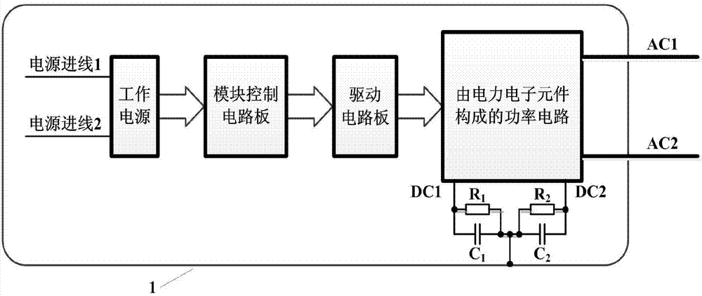
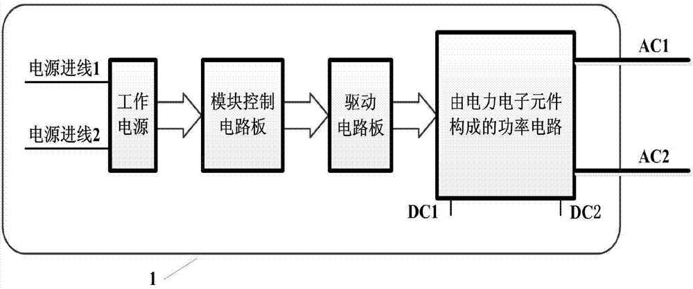
[0036] When the working power supply of the power module is an AC power supply, a transformer is used as the working power supply in this embodiment. The incoming line of the primary side of the transformer can be the AC power supply outside the power module, or the AC output of the power module; the secondary outgoing line of the transformer is connected to Working power supply, the output of the working power supply is connected to the module control circuit board.

[0037] see Figure 5 As shown, the first capacitor C1 is connected between the metal casing 1 of the power module and any incoming line of the working power supply (in this embodiment, taking the incoming line 2 as an example), and at the same time, the metal casing 1 of the power module and the power module The second capacitor C2 is connected across any AC outgoing line (in this embodiment, AC2 is taken as an example), and the first capacitor C1 and the second capacitor C2 together form a protection circuit. ...

Embodiment 2

[0050] The difference between this embodiment and Embodiment 1 lies in that: the working power supply in the power module is powered by a DC power supply, taking the power supply of the DC busbars DC1 and DC2 of the power module as an example. In this case, the first capacitor C1 can be connected between the metal casing 1 of the power module and any incoming line of the working power supply. The protection circuit is simple, the structure is compact, and the original structural design of the power module is not affected.

[0051] like Figure 11 As shown, the working power supply line 1 is connected to the DC bus DC2 , the working power supply line 2 is connected to the DC bus DC1 , and the first capacitor C1 is connected between the working power supply line 1 and the metal casing 1 . like Figure 12 As shown, the first resistor R1 is connected in parallel next to the first capacitor C1 as its discharge branch.

[0052] Since the radiator is fixed on the metal casing 1 of ...


PUM


Abstract

The invention discloses a protection circuit of a middle / high voltage current converter power module. A capacitor (C1) is connected between a metal shell of a power module and a working power supply in a spanning manner, according to different power supply modes of the working power supply of the power module, a capacitor (C2) also can be selectively connected between the metal shell of the power module and an outlet end of the power module in the spanning manner, so that a group of protection circuits are formed, and the influence of spurious charge is eliminated; to further enhance the function in eliminating the spurious charge, resistors can be connected beside the capacitors in parallel, and the resistors can be used as release branches of the capacitors. The protection circuit disclosed by the invention is compact in structure, the original structural design of the power module is not affected, the potential difference among components such as a driving circuit board, a module control circuit board and the working power supply and the metal shell can be effectively reduced, potential safety hazard is eliminated, and the security of the power module is improved.

Description

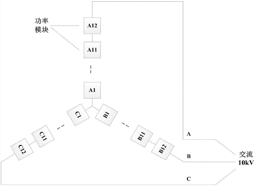
technical field [0001] The present invention relates to a protection circuit, in particular to a protection circuit for a power module of a medium and high voltage converter. Background technique [0002] At present, my country is actively promoting the construction of a strong smart grid, and flexible high-voltage DC transmission is an important part of realizing the smart grid. In a flexible high-voltage direct current transmission (VSC-HVDC) system, it usually consists of two or more converter stations and DC transmission lines, and the AC side of the converter station is connected to the AC system. The converter station at one end rectifies the three-phase AC power into DC power, and then sends it to the converter station at the other end through the DC transmission line, and the converter station inverts the DC power into three-phase AC power. The main advantage of flexible DC transmission technology is that it does not increase the short-circuit capacity of the system...

Claims


Application Information

Patent Timeline
Patent Type & Authority Applications(China)
IPC IPC(8): H02M1/32
Inventor 张春朋
Owner TSINGHUA UNIV
Learn More