
Multifunctional constant-volume bomb for testing spraying, burning and soot generation characteristics

A technology of constant volume bombs and soot, applied in the direction of measuring devices, material analysis through optical means, instruments, etc., can solve problems such as heating, force asymmetry, explosion, and deformation of bombs, and achieve flexible and convenient layout. Improve experimental efficiency and simple structure

Active Publication Date: 2014-04-02
SHANGHAI JIAO TONG UNIV
View PDF6 Cites 27 Cited by
  • Summary
  • Abstract
  • Description
  • Claims
  • Application Information

AI Technical Summary

Problems solved by technology

The bomb capacity of this structure is relatively simple, but the experimental efficiency is low
Because there will be intervals between two experiments, repeated cycles of inflation-heating-deflation-reinflation-reheating are required, the experiment takes a long time, and the target temperature and its uniformity are difficult to control
[0008] Second, it is difficult to reach a high enough temperature and pressure in the test working condition
For example, the temperature and pressure of the supercharged diesel engine near the top dead center can reach about 1100K and 10MPa, but the currently designed constant volume bullets can rarely reach the temperature and pressure before combustion in the cylinder of the supercharged engine, thus limiting the use of constant volume bombs. The bomb is used to simulate and test the spray and combustion conditions in the cylinder of a diesel engine. The main reason is that the heat and force of each part of the bomb are asymmetrical under high temperature and high pressure test conditions, which easily deforms the bomb body and further damages the glass of the optical window. shatter and explode
[0009] Third, the scope of testing is not wide enough
That is, it cannot be applied to spray and combustion tests under various conditions
In terms of spray testing, it is mostly due to structural design that the position of the injector and the arrangement of the optical path cannot be adjusted flexibly; in terms of combustion testing, as mentioned above, it is difficult to further increase the experimental temperature and pressure mainly limited to the bomb.
[0010] For example, the patent "a constant volume bomb for spray testing" (patent application number 201010272629.3) claims that continuous testing can be achieved, but due to the structural design of the bomb, the fuel injector can only be installed on the upper cover of the bomb. The optical window can only be installed in the circumferential direction of the bomb
Such a design makes it possible for the bomb to measure the axial plane light of the spray, but it cannot measure the distribution of the cross-sectional fuel drop point, and it is also difficult to test the droplet size with a phase Doppler (PDI) analyzer, which reduces the The test range of the bomb; and the bomb can only be used for the spray test, not the combustion test, because the strength and safety of the bomb can not be effectively guaranteed because of the uneven force and heat of each part of the bomb under the high temperature and high pressure test conditions

Method used


Image

  • Multifunctional constant-volume bomb for testing spraying, burning and soot generation characteristics
  • Multifunctional constant-volume bomb for testing spraying, burning and soot generation characteristics
  • Multifunctional constant-volume bomb for testing spraying, burning and soot generation characteristics

Examples


Embodiment Construction

[0034] The present invention will be described in detail below in conjunction with the accompanying drawings and embodiments, but the protection scope of the present invention should not be limited thereto.

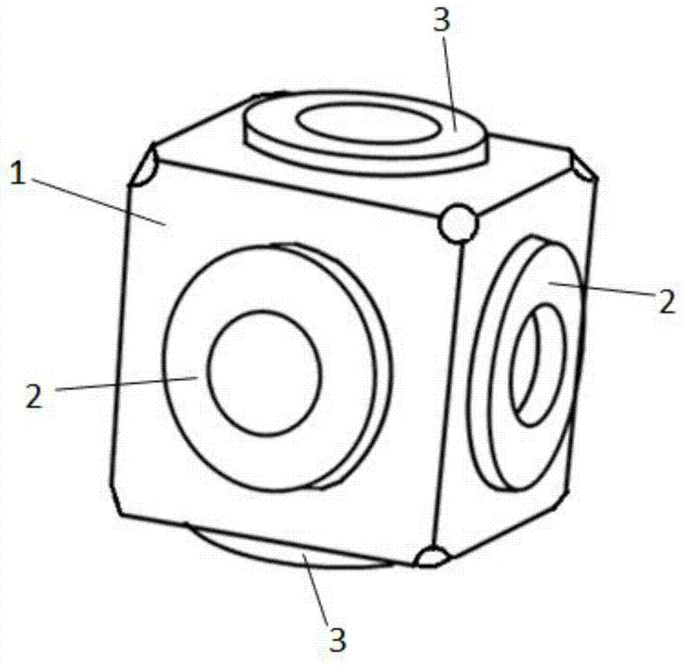
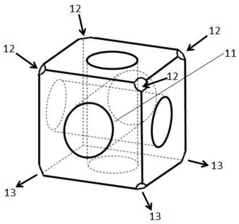
[0035] A kind of constant volume bomb used for spraying, combustion and soot generation characteristics test provided by the present invention, the assembly schematic diagram is as follows figure 1 As shown, it mainly includes: a bomb containing body 1, an optical window 2 (there are four in this embodiment, arranged in the circumferential direction, and two are shown in the figure), an end cover 3 and an air inlet heating system (the air inlet heating system is set on On the outside of each air inlet of the main body, the constant volume bomb is used to heat the air intake during the high temperature test, which is not shown in the figure and will be described below). The four optical windows and the two end caps are respectively connected to the six surfaces of the body...


PUM


Abstract

The invention discloses a multifunctional constant-volume bomb for testing spraying, burning and soot generation characteristics. The multifunctional constant-volume bomb comprises a body and two to six optical windows, wherein the body is simple in structure, and the optical windows is protected by double-layer glass (namely thick pressure-bearing glass and thin thermal-insulation glass) and an air thermal-protective layer, so that a stable high-temperature high-pressure test environment is provided. The multifunctional constant-volume bomb provided by the invention has the characteristics that the structure is compact, the structure is simple, the processing is convenient, the arrangement of an optical system and an ejector is flexible, and light guiding grooves are formed in fixators of the optical windows and are suitable for continuously measuring by using a phase Doppler method under a high-temperature and high-pressure condition; the constant-volume bomb provided by the invention is used for applying one and a combination of a plane laser induced fluorescence method (spraying section fuel oil droppoint distribution and the like), a laser induced phosphorescence method (temperature distribution of a gas-phase and a wall surface), a laser absorbing and scattering method (gas-liquid two-phase concentration field, air-fuel ratio distribution and the like), a laser induced flaming method (soot), a schlieren method on the spraying, burning and soot generation characteristics and the like, simultaneously measuring the spraying, burning and soot generation characteristics and the like, and the multifunctional constant-volume bomb has a universality property.

Description

technical field [0001] The invention belongs to the technical field of heat engines, and relates to a constant-volume bomb used for fuel spray and combustion tests, in particular to a device that can generate a gas environment (pressure, temperature, composition) similar to an internal combustion engine cylinder, and can carry out The process of atomization, evaporation, mixture formation, combustion, soot generation and other tests and tests of various characteristics of fuel spray. Background technique [0002] The fuel spray characteristics of the engine are one of the most important factors affecting the performance of the engine, and for high-pressure direct injection gasoline engines, the spray characteristics have a great impact on the engine combustion and emission performance. Therefore, the test of the spray characteristics of the fuel injection system is of great significance to the design and development of the engine combustion system. [0003] In the research ...

Claims


Application Information

Patent Timeline
IPC IPC(8): G01N21/00G01N21/01
Inventor 张玉银林柏洋吴胜奇李世琰
Owner SHANGHAI JIAO TONG UNIV
Learn More