Artificial vibrator real-time monitoring and positioning system

A real-time monitoring and positioning system technology, which is applied in infrastructure engineering, architecture, building construction, etc., can solve problems such as difficult continuous supervision and vibration, low positioning accuracy, difficult accurate identification, real-time correction of deviation traceability, etc., to avoid Leakage phenomenon, effect of auxiliary control

Active Publication Date: 2016-06-01
CHINA HYDROELECTRIC ENGINEERING CONSULTING GROUP CHENGDU RESEARCH HYDROELECTRIC INVESTIGATION DESIGN AND INSTITUTE
View PDF10 Cites 0 Cited by
  • Summary
  • Abstract
  • Description
  • Claims
  • Application Information

AI Technical Summary

Problems solved by technology

[0004] The existing technology mainly relies on the side station supervision to judge the concrete vibrating process through side station observation. The position of the manual vibrator is determined by referring to the visual distance of relatively fixed objects in the warehouse surface. The positioning accuracy is low, and it is difficult to supervise the whole process and continuously During the vibrating process, there are prone to seam lap joints and disorderly vibrating phenomena; and the positioning process of the vibrating machine is mainly qualitative, which is obviously affected by personal subjective factors and lacks accurate data support
If there are seam lap joints and vibration leakage caused by disorderly vibration during the construction process, it will be difficult to accurately identify, correct deviations in real time, and trace back afterwards
This is not conducive to the management of vibrating construction quality, and it is difficult to effectively ensure the quality of concrete pouring construction

Method used


Image

  • Artificial vibrator real-time monitoring and positioning system

Examples


Embodiment Construction

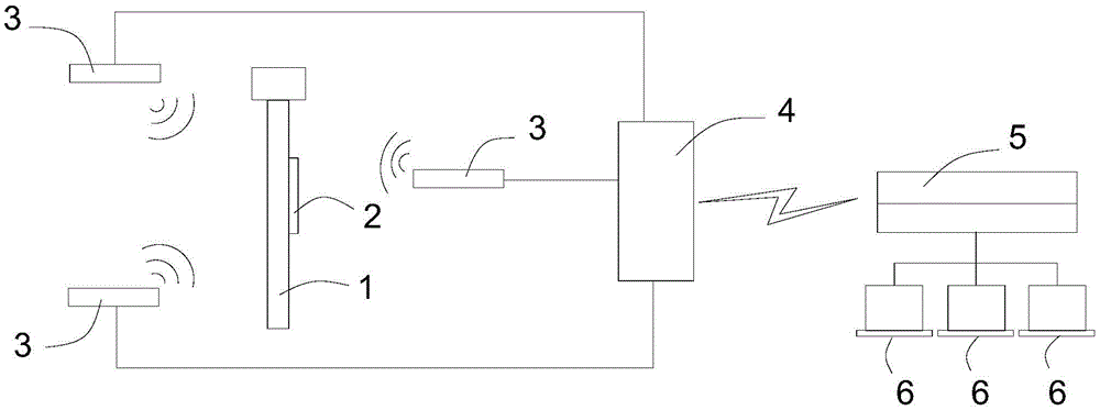
[0014] Such as figure 1 The real-time monitoring and positioning system of the artificial vibrator of the present invention includes an artificial vibrator 1, a wireless signal transmitter 2 of an ultra-wideband active signal is provided on the artificial vibrator 1, and a wireless signal transmitter 2 is provided on the wireless signal transmitter 2. A battery is provided to provide power for the wireless signal transmitting device 2 . The wireless signal transmitting device 2 sends information including its own number in real time. There are at least three wireless signal receiving devices 3 in the concrete pouring construction area (such as the warehouse surface), and the receiving range of the wireless signal receiving device 3 needs to completely cover the manual vibration construction area. The synchronization controller 4 is connected by wire to synchronize the time of the wireless signal receiving device 3 to ensure that the three-dimensional coordinates of the artifi...


PUM


Abstract

The invention relates to a real-time vibrating bar monitoring and positioning system which comprises a manual vibrating bar. A wireless signal transmitting device is arranged on the manual vibrating bar, at least three wireless signal receiving devices are arranged in a concrete pouring construction region and transmit received signals to a server, and the signals are transmitted by the wireless signal transmitting device. The real-time manual vibrating bar monitoring and positioning system has the advantages that accurate three-dimensional coordinate information of the manual vibrating bar can be acquired in real time during concrete construction, so that an excellent foundation can be laid for monitoring the manual vibrating quality; the real-time manual vibrating bar monitoring and positioning system further can be combined with other manual vibrating quality monitoring solutions, so that other monitoring data can be acquired, construction management staff can be effectively assisted in controlling the concrete vibrating construction quality, and phenomena of miss vibrating can be prevented.

Description

technical field [0001] The invention relates to a system for controlling the construction quality of concrete pouring in water conservancy projects, in particular to a real-time monitoring and positioning system for artificial vibrating rods. Background technique [0002] Concrete vibration is the key process of concrete pouring, and the monitoring and control of vibration quality in the process is one of the important links of concrete quality control. At present, the vibrating quality control on the construction site ensures the full coverage of the concrete pouring area through the staggered insertion of the vibrating rods. Pound densely. The general empirical control method is as follows: construction personnel vibrate in order according to the strip direction. However, in actual construction, there is often a phenomenon that the construction does not follow the strip method, which is easy to increase the interference between the various processes, especially in the vi...

Claims


Application Information

Patent Timeline
Patent Type & Authority Patents(China)
IPC IPC(8): E02D15/02E04G21/08
Inventor 尹习双刘金飞钟桂良宋述军
Owner CHINA HYDROELECTRIC ENGINEERING CONSULTING GROUP CHENGDU RESEARCH HYDROELECTRIC INVESTIGATION DESIGN AND INSTITUTE
Why Eureka
Try Eureka