
Free forging oil press rack

A technology for hydraulic presses and racks, applied in forging/pressing/hammering machinery, forging/pressing/hammer devices, manufacturing tools, etc., can solve the problems of complex internal structure, easy generation of waste, long construction period, etc. The effect of short manufacturing cycle and shortened production cycle

Inactive Publication Date: 2014-04-02
SHENYANG CHAOZHONG ENG DESIGN
View PDF12 Cites 3 Cited by
  • Summary
  • Abstract
  • Description
  • Claims
  • Application Information

AI Technical Summary

Problems solved by technology

[0002] With the continuous development of contemporary electric power, steel, petrochemical, weapons and other industries, the demand for large-scale equipment in foreign and domestic markets is increasing, such as large-scale nuclear power parts, parts required by military industry, and aerospace parts. Parts usually need to be processed by a hydraulic press, while the frame of a traditional hydraulic press, for example, the frame of a large free-forging hydraulic press, is made of steel castings. After the size of the processed parts is increased, the size of the frame of the hydraulic press It is also increasing. Due to the heavy weight of each component of the frame and the complex internal structure, higher requirements are placed on the casting equipment when manufacturing this frame, and the casting process will be more stringent, resulting in more manufacturing processes and lower costs. High, long construction period, easy to produce waste products, so a new process has to be considered to manufacture the frame of large free forging hydraulic press

Method used


Image

  • Free forging oil press rack
  • Free forging oil press rack
  • Free forging oil press rack

Examples


example 1

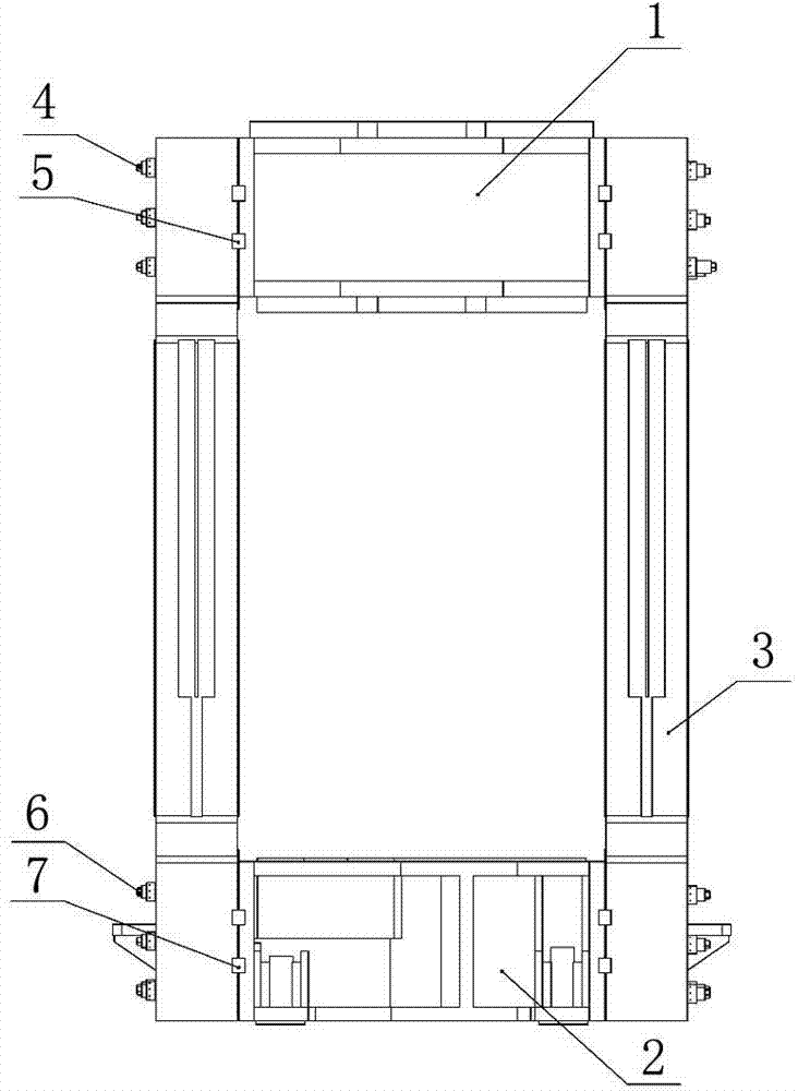
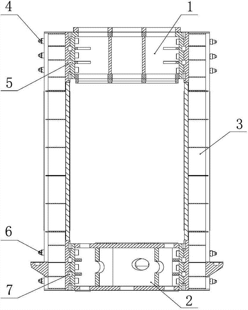
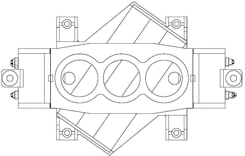
[0017] First, the technical solution provided by the present invention is applied to the frame of the 40MN free forging hydraulic press. As mentioned above, the frame includes an upper beam 1, a lower beam 2 and two columns 3 made by welding, and the upper beam 1. The shape and structure of the lower crossbeam 2 and the upright column 3 are basically similar to those of the parts of the frame obtained by casting. Wherein, the two columns 3 are vertically arranged symmetrically on both sides of the frame, the upper beam 1 is placed on the top of the frame and between the two columns 3, and the upper beam 1 is preloaded by the upper beam pull rod 4 Assembled together, a plurality of upper beam rectangular keys 5 are embedded in the rectangular key grooves reserved at the upper ends of the upper beam 1 and the two columns 3 . The lower crossbeam 2 is placed at the bottom of the frame and also between the two uprights 3, and is preloaded and assembled together by the lower beam ti...


PUM


Abstract

The invention discloses a free forging oil press rack. The free forging oil press rack comprises an upper cross beam (1), a lower cross beam (2) and two upright columns (3), which are formed by a welding process, wherein the two upright columns (3) are vertically symmetrically arranged at two sides of the free forging oil press rack; the upper cross beam (1) is arranged at the top of the free forging oil press rack, is positioned between the two upright columns (3) and is pre-tightened and assembled together with the two upright columns by upper beam pull rods (4); multiple upper beam rectangular keys (5) are embedded in rectangular key slots reserved in the upper ends of the upper cross beam (1) and the upright columns (3); the lower cross beam (2) is arranged at the bottom of the free forging oil press rack, is positioned between the two upright columns (3) and is pre-tightened and assembled together with the two upright columns by lower beam pull rods (6); multiple lower beam rectangular keys (7) are embedded in rectangular key slots reserved at the lower ends of the lower cross beam (2) and the upright columns (3). The free forging oil press rack has the advantages of simple structure, light weight, low cost, short manufacturing period, easiness in manufacturing and machining and the like.

Description

technical field [0001] The invention belongs to the technical field of hydraulic presses, in particular to a free forging hydraulic press frame. Background technique [0002] With the continuous development of contemporary electric power, steel, petrochemical, weapons and other industries, the demand for large-scale equipment in foreign and domestic markets is increasing, such as large-scale nuclear power parts, parts required by military industry, and aerospace parts. Parts usually need to be processed by a hydraulic press, while the frame of a traditional hydraulic press, for example, the frame of a large free-forging hydraulic press, is made of steel castings. After the size of the processed parts is increased, the size of the frame of the hydraulic press It is also increasing. Due to the heavy weight of each component of the frame and the complex internal structure, higher requirements are placed on the casting equipment when manufacturing this frame, and the casting pro...

Claims


Application Information

Patent Timeline
IPC IPC(8): B21J13/04
Inventor 李云龙宋国峰王玉杰王宏建李跃刚李维平向东
Owner SHENYANG CHAOZHONG ENG DESIGN
Learn More