RS422 transmitting-receiving bidirectional monitoring circuit

A RS485, circuit technology, applied in the field of RS422 transceiver two-way monitoring circuit, can solve problems such as difficult fault points, increase difficulty in troubleshooting, and achieve the effect of stable and effective work and simplified circuit

Active Publication Date: 2014-03-26
BEIJING JINGYI QIANGYUAN TECH
View PDF3 Cites 0 Cited by
  • Summary
  • Abstract
  • Description
  • Claims
  • Application Information

AI Technical Summary

Problems solved by technology

However, if the video broadcast controller is connected to a video device with a weak or no communication recording function such as a video recorder, a switcher, or a matrix, it is difficult to accurately determine where the fault point is when a fault occurs, which adds more time to troubleshooting. difficulty

Method used


Image

  • RS422 transmitting-receiving bidirectional monitoring circuit
  • RS422 transmitting-receiving bidirectional monitoring circuit
  • RS422 transmitting-receiving bidirectional monitoring circuit

Examples


Embodiment 1

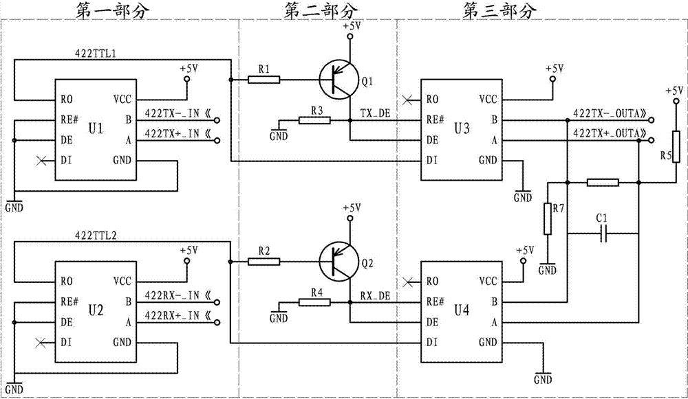
[0018] This embodiment is a RS422 transceiver two-way monitoring circuit, such as figure 1 shown. This embodiment includes: receiving the sender signal ( figure 1 The RS485 transceiver chip U1, which is represented by 422TX+_IN "and 422TX-_IN ", receives the receiver signal ( figure 1 The RS485 transceiver chip U2 of 422RX+_IN "and 422RX-_IN "indicated), the RS485 transceiver chip U3 of the sender signal, the RS485 transceiver chip U4 of the receiver signal, the control transistor Q1, and the control transistor Q2; The A pin and B pin of U1 are respectively connected to the positive and negative terminals of the sender signal, the RO pin of the U1 is connected to the DI pin of the U3, and the RO pin of the U1 is connected to the Q1 through the current limiting resistor R1. The base of the Q1 is connected to the base of the Q1, the RE# pin and the DE pin of the U3 are connected; the A pin and the B pin of the U2 are respectively connected to the positive and negative terminal...

Embodiment 2

[0032] This embodiment is an improvement of Embodiment 1, and it is a refinement of Embodiment 1 regarding the addition of the output signal shaping circuit, such as Figure 5 shown. The positive end of the bypass signal described in this embodiment ( Figure 5 Indicated by 422TX+_OUTA "), it is connected to the A pin of the shaping input chip U5, and the negative terminal of the bypass signal ( Figure 5 422TX-_OUTA (indicated by 422TX-_OUTA) is connected to the B pin of the shaping input chip U5, the RO pin of the U5 is connected to the DI pin of the shaping output chip U6, and the A and B pins of the U6 are respectively the bypass signal after shaping. Positive and negative output terminals ( Figure 5 Indicated by 422TX+_OUT "and 422TX-_OUT".

[0033] In this embodiment, the output 422TX+_OUTA and 422TX-_OUTA of the third part of the circuit are connected to a pair of serial port transceiver chips, which are converted into TTL level by the RS485 transceiver chip again a...

Embodiment 3

[0035] This embodiment is an improvement of the second embodiment, and is a refinement of the clamping resistor of the second embodiment. The capacitor C1 is connected in parallel with both ends of the resistor R6 described in this embodiment.

[0036] The use of capacitor C1 can suppress the high-frequency interference at its two ends, making the signal more stable.


PUM


Abstract

The invention relates to a RS422 transmitting-receiving bidirectional monitoring circuit. The RS422 transmitting-receiving bidirectional monitoring circuit comprises transmitting-receiving chips U1-U4, and control triodes Q1 and Q2, wherein a pin A and a pin B of the U1 are connected to a positive end and a negative end of a signal transmitting party respectively; a pin RO of the U1 is connected to a pin DI of the U3; a pin RO of the U1 is connected to the base electrode of the Q1 through a current limiting resistor R1; the collector electrode of the Q1 is connected to a pin RE# and a pin DE of the U3; a pin A and a pin B of the U2 are connected to a positive end and a negative end of a signal receiving party; a pin RO of the U2 is connected to a pin DI of the U4; a pin RO of the U2 is connected to the base electrode of the Q2 through a current limiting resistor R2. According to the invention, a TTL (Transistor-Transistor Logic) signal is divided into two portions for treatment, one portion serves as a communication signal while the other portion forms a control signal for transmitting-receiving DEs (Decision Element) of the U3 and the U4 through a control circuit. The whole circuit is very simple, the operation is steady and efficient, the data in both the transmitting and receiving directions of a serial port are monitored at the same time, and communication of the monitored serial port is not affected.

Description

technical field [0001] The present invention designs a RS422 transceiver bidirectional monitoring circuit, which is an electronic circuit, and is a circuit capable of simultaneously monitoring the RS422 transceiver bidirectional direction without affecting the monitored serial port communication. Background technique [0002] In order to ensure the safety of broadcasting, the digital TV broadcasting system usually sets up two sets of video broadcasting control systems, master and backup. In order to realize the switching between the main system and the backup system, it is necessary to add a switch between the main and backup systems. During normal broadcasting, the switcher will connect to the main control channel, so the main and standby video servers (including broadcasting online switcher, broadcasting video recorder and other equipment) are controlled by the main broadcasting The workstation communicates with the main broadcast control workstation through the core jump...

Claims


Application Information

Patent Timeline
Patent Type & Authority Applications(China)
IPC IPC(8): H04N17/00H04H60/29
Inventor 臧席宇商同尚振华佟洪波毛远霓王付生
Owner BEIJING JINGYI QIANGYUAN TECH
Why Eureka
Try Eureka