Filter circuit efficient in filtering

A filter circuit and high-efficiency technology, applied in the field of filters, can solve problems such as resonance phenomenon, large influence of system parameters, unfavorable development of microwave communication, etc., and achieve the effect of improving quality and transmitting accurate signals

Inactive Publication Date: 2014-03-26
成都威势科技有限公司
View PDF3 Cites 1 Cited by
  • Summary
  • Abstract
  • Description
  • Claims
  • Application Information

AI Technical Summary

Problems solved by technology

The characteristics of the existing filter circuit are greatly affected by system parameters, and can only eliminate specific harmonics, but will amplify some harmonics, and even cause resonance, which is not conducive to microwave communication
In addition, there are also filter circuits that do not generate resonance, but the bandwidth of the integrated operational amplifier is limited, making it difficult to make the operating frequency of the filter circuit very high
However, microwave communication has been widely used because of its frequency bandwidth, large capacity, and can be used for the transmission of various telecommunication services. The existing filter circuits have great defects, which are not conducive to the development of microwave communication.

Method used


Image

  • Filter circuit efficient in filtering

Examples


Embodiment

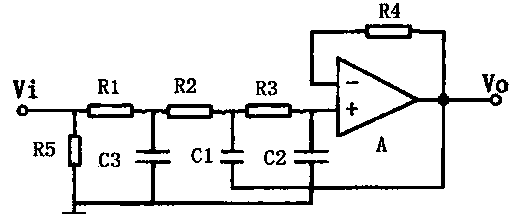
[0014] like figure 1 As shown, the present invention includes resistor R1, resistor R2, resistor R3, resistor R4, resistor R5, capacitor C1, capacitor C2, capacitor C3, operational amplifier A, AC power supply Vi and DC power supply V0, described AC power supply Vi, resistor R1, resistor R2, resistor R3 and the non-inverting input terminal of the operational amplifier A are sequentially connected in series. In this embodiment, one end of the capacitor C1 is connected to the common end of the resistor R2 and the resistor R3, and the other end is connected to the output end of the operational amplifier A; one end of the capacitor C2 is connected to the common end of the resistor R3 and the operational amplifier A, and the other end is connected to the capacitor C3; the capacitor C3 is also Connect the common terminal of resistor R1 and resistor R2. Among the capacitors C1, C2 and C3, the capacitor C3 has the smallest capacity, the capacitor C1 has the largest capacity, and the ...


PUM

PropertyMeasurementUnit
Resistanceaaaaaaaaaa

Abstract

The invention discloses a filter circuit efficient in filtering. The filter circuit comprises a resistor R1, a resistor R2, a resistor R3, a resistor R4, a resistor R5, a capacitor C1, a capacitor C2, a capacitor C3, an operation amplifier A, an alternating-current power supply Vi and a direct-current power supply V0. The non-inverting input ends of the alternating-current power supply Vi, the resistor R1, the resistor R2, the resistor R3 and the operation amplifier A are sequentially serially connected. One end of the capacitor C1 is connected to the common terminal of the resistor R2 and the resistor R3, and the other end thereof is connected with the output end of the operation amplifier A. One end of the capacitor C2 is connected with the common terminal of the resistor R3 and the operation amplifier A, and the other end thereof is connected with the capacitor C3. The capacitor C3 is further connected with the common terminal of the resistor R1 and the resistor R2. One end of the resistor R5 is connected with the common terminal of the alternating-current power supply Vi and the resistor R1. The resistor R5, the capacitor C2 and the capacitor C3 are all grounded. The resistor 4 is connected between an inverting input end of the operation amplifier A and the output end of the operation amplifier A. The output end of the operation amplifier A is further connected with the direct-current power supply V0. By the arrangement, twice filtering can be achieved, signal transmission is accurate, resonance phenomena can be avoided, and microwave communication quality can be increased.

Description

technical field [0001] The invention relates to the field of filters, in particular to a filter circuit for high-efficiency filtering. Background technique [0002] Filter is an electrical component that reduces or eliminates the influence of harmonics on the power system. A filter is a device used to eliminate interference noise, which filters the input or output to obtain pure direct current. A circuit that effectively filters out a frequency point of a specific frequency or frequencies other than this frequency point is a filter, and its function is to obtain a specific frequency or eliminate a specific frequency. In the field of microwave communication, it is often necessary to filter the transmitted electromagnetic waves to retain electromagnetic waves with a wavelength between 0.1 mm and 1 meter. Filter circuits are also required in this process. The characteristics of existing filter circuits are greatly affected by system parameters, and can only eliminate specific...

Claims


Application Information

Patent Timeline
IPC IPC(8): H03H7/01H03H11/04
Inventor 林海廉保旺高瑜翔
Owner 成都威势科技有限公司
Why Eureka
Try Eureka