
Fiber and space hybrid regenerative laser amplifier

A laser amplifier and regenerative amplifier technology, applied in the field of lasers, can solve problems such as laser loss, achieve the effects of ASE suppression, simple structure, and ensure output energy stability

Active Publication Date: 2016-06-08
SHANGHAI INST OF OPTICS & FINE MECHANICS CHINESE ACAD OF SCI
View PDF4 Cites 0 Cited by
  • Summary
  • Abstract
  • Description
  • Claims
  • Application Information

AI Technical Summary

Problems solved by technology

When the optical power transmitted inside the fiber reaches a certain threshold, the above two nonlinear effects will occur, causing a large amount of laser energy to be converted into Stokes light and lost.

Method used


Image

  • Fiber and space hybrid regenerative laser amplifier
  • Fiber and space hybrid regenerative laser amplifier
  • Fiber and space hybrid regenerative laser amplifier

Examples


Embodiment Construction

[0024] The present invention will be further described below in conjunction with the embodiments and accompanying drawings, but the protection scope of the present invention should not be limited thereby.

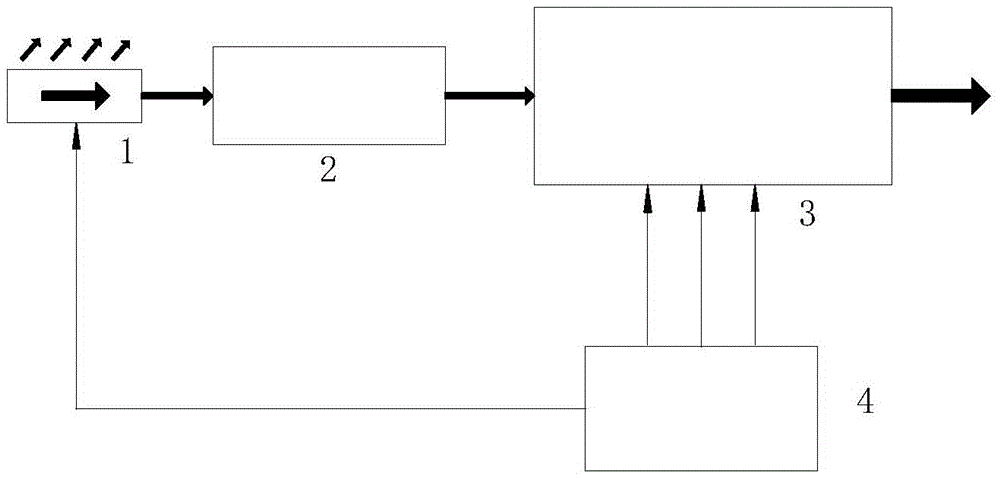
[0025] see first figure 1 , figure 1 It is a frame diagram of the overall structure of the fiber space hybrid regenerative amplifier of the present invention. It can be seen from the figure that the present invention is composed of a pulse light source 1 , an energy injection unit 2 , a regenerative amplifier unit 3 and a synchronous control unit 4 .

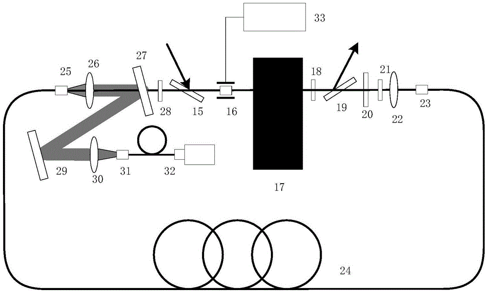
[0026] For a schematic structural diagram of the energy injection unit 2, see figure 2 . . It can be seen from the figure that the pulsed laser light emitted by the light source 1 passes through the polarization controller 5, the first one-way isolator 6, the second one-way isolator 7, the 9:1 beam splitter 8, the aspheric lens 10, and the film polarizer 11 , a half-wave plate 12, and a Faraday rotator 13, and then ente...


PUM


Abstract

An optical fiber and space mixing regeneration laser amplifier comprises a pulse light source, an energy injection unit, a regeneration amplifier unit, a phase control unit and a synchronous control unit. The optical fiber and space mixing regeneration laser amplifier is characterized in that optical fibers are used as amplifier gain media, and the problem that repetition frequency cannot be improved caused by body material heat effect can be well solved. A body phase modulator is added into a regeneration cavity, light pulses are amplified, meanwhile, the spectrum is subjected to modulation and broadening, and the nonlinear threshold value of the optical fibers is improved, so that the effect of energy output improving is achieved. Due to the coiling performance of the optical fibers, miniaturization of the regeneration amplifier can be achieved. The functions of the high-gain high-stability regeneration amplifier and the multi-pass phase modulator are integrated.

Description

technical field [0001] The invention relates to a laser, in particular to a regenerative laser amplifier mixed with optical fiber and space. Background technique [0002] In the field of high-power laser research, pulsed lasers are required, and the time waveform, pulse width and spectral characteristics of pulsed lasers are required to be controlled. The MOPA structure solves this problem very well. It separates the main oscillator from the power amplifier. , where the main oscillator realizes the control of the laser pulse time and spectral characteristics, and the power amplifier completes the amplification of the laser pulse power and energy. [0003] High-power laser amplifiers often adopt the form of multi-stage amplification. With the continuous amplification of the laser pulse in the amplifying medium, the fluctuation introduced by the injection seed laser itself decreases the stability of the output energy of the amplifier. The regenerative amplifier is a single-d...

Claims


Application Information

Patent Timeline
Patent Type & Authority Patents(China)
IPC IPC(8): H01S3/107H01S3/067H01S3/23
Inventor 彭宇杰李学春王江峰汪小超黄文发张玉奇
Owner SHANGHAI INST OF OPTICS & FINE MECHANICS CHINESE ACAD OF SCI
Learn More