
System and method for measuring direct tensile strength and deformation of rock

A measurement system and tensile strength technology, applied in the direction of electric/magnetic solid deformation measurement, measurement device, strength characteristics, etc., can solve problems such as bending or torsional stress, easy to generate bending moment, easy to generate stress concentration effect at the end, etc.

Inactive Publication Date: 2014-03-26
UNIV OF SCI & TECH BEIJING
View PDF5 Cites 29 Cited by
  • Summary
  • Abstract
  • Description
  • Claims
  • Application Information

AI Technical Summary

Problems solved by technology

[0008] The above conditions have the following problems in actual operation: First, the process of bonding the sample to the metal cap is carried out manually, and the parallelism is difficult to grasp. If the parallelism does not meet the requirements, bending moments are likely to occur during the test ; Secondly, the strength of the adhesive used in the sample must be greater than the tensile strength of the rock, otherwise it will be damaged along the sticking place during the test instead of the tensile failure of the rock; in addition, after the rock sample is bonded, it is easy to Stress concentration effect is generated; after the final test machine clamps the bonded rock sample, bending or torsional stress will be generated in most cases, resulting in test failure
During the test of this system, the end effect will be generated at the joint between the end of the sample and the metal cap, and a stress concentration point will be generated at the end, and the sample will often break along the joint.

Method used


Image

  • System and method for measuring direct tensile strength and deformation of rock
  • System and method for measuring direct tensile strength and deformation of rock
  • System and method for measuring direct tensile strength and deformation of rock

Examples


Embodiment Construction

[0040] Technical effects of embodiments of the present invention will be apparent with reference to the following description and accompanying drawings. In these descriptions and drawings, some specific implementations of the embodiments of the present invention are specifically disclosed to represent some ways of implementing the principles of the embodiments of the present invention, but it should be understood that the scope of the embodiments of the present invention is not limited by this limit. On the contrary, the embodiments of the present invention include all changes, modifications and equivalents coming within the spirit and scope of the appended claims.

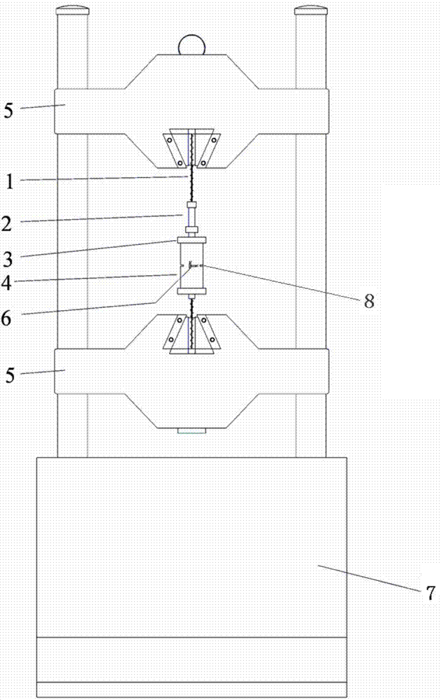
[0041] The measurement system for direct tensile and deformation measurement of rocks using artificial incisions according to the present invention will be described below with reference to the accompanying drawings.

[0042] Such as figure 1 As shown, the structure of the measuring system for rock direct stretc...


PUM

PropertyMeasurementUnit
Diameteraaaaaaaaaa
Widthaaaaaaaaaa

Abstract

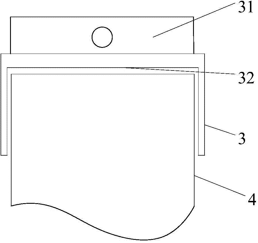
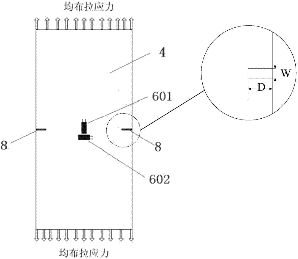
The invention provides a system and a method for measuring direct tensile strength and deformation of rock by using manual kerfs. The system comprises test loading equipment, a rock sample, metal sleeve caps, a flexible connecting mechanism and a tensile load sensor, wherein the rock sample is cylindrical, two kerfs are symmetrically cut in two sides of the middle position of the rock sample, and the kerf directions are the radial direction of the sample; and an upper metal sleeve cap and a lower metal sleeve cap are arranged at two ends of the rock sample respectively, the upper metal sleeve cap is connected with an upper clamp clamping opening of the test loading equipment through the flexible connecting mechanism and the tensile load sensor sequentially, and the lower metal sleeve cap is connected with a lower clamp clamping opening of the test loading equipment 7 through the flexible connecting mechanism. According to the technical scheme, the defects that the rock sample is prone to bend or produce torsion stress in a direct tensile test are overcome, at the same time, the situation that tensile fracture is not produced during fracture due to the end stress concentration effect of the rock sample is avoided, and the rock tensile strength and the axial and radial deformation of the rock in a stretching process can be accurately and effectively measured.

Description

technical field [0001] The invention relates to the field of measurement and testing of solid materials, in particular to a system and method for directly measuring the tensile strength and deformation of rocks by using artificial incisions. Background technique [0002] The tensile strength of the rock refers to the maximum tensile stress that the rock can withstand when it reaches failure under the action of uniaxial tensile load, which is called the uniaxial tensile strength of the rock (Tensile strength), referred to as the tensile strength. [0003] At present, there are two main experimental methods for measuring the tensile strength of rocks: the indirect stretching method and the direct stretching method. The indirect tensile method mainly adopts the method of Brazilian splitting, adopts a disc-shaped specimen (height-to-diameter ratio 1:2), and applies a load in the diameter direction of the specimen to cause damage along the diameter direction of the specimen. The...

Claims


Application Information

Patent Timeline
IPC IPC(8): G01N3/08G01N3/06G01B7/16
Inventor 张磊黄正均王宝学杨同刘钰
Owner UNIV OF SCI & TECH BEIJING
Learn More