Thread anti-bending mechanism

An anti-bending and threading technology, which is applied in the direction of threaded fasteners, nuts, bolts, etc., can solve problems such as uneven axial load distribution, cylindrical fatigue, fracture, etc., achieve flexible and controllable position and degree, and reduce bending , Weaken the effect of the force on the annular surface

Active Publication Date: 2016-01-06
HAITIAN PLASTICS MACHINERY GRP
View PDF7 Cites 0 Cited by
  • Summary
  • Abstract
  • Description
  • Claims
  • Application Information

AI Technical Summary

Problems solved by technology

In the existing thread mechanism, the cylinder and the nut basically provide tensile load through thread engagement, and the axial load in the structure is all borne by the cylinder thread, and the cylindrical thread section is inevitably stressed due to materials, processing and other reasons. , the distribution of the axial load on each screw thread is uneven, especially when it is applied to the support plate, the shear force acting on the thread part of the cylinder when the support plate is bent and deformed is very bad, resulting in the rapid fatigue of the cylinder, and finally fail to break

Method used


Image

  • Thread anti-bending mechanism
  • Thread anti-bending mechanism
  • Thread anti-bending mechanism

Examples


Embodiment Construction

[0026] The present invention will be further described below with reference to the embodiments of the drawings, taking the threaded anti-bending mechanism as a pull rod mechanism as an example, and applying the pull rod mechanism to an injection molding machine head template.

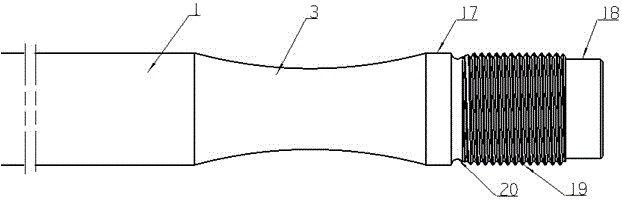
[0027] like figure 1 As shown, a threaded section 19 is provided at the head of the tie rod 1 of the injection molding machine, and a fulcrum section 17 and a fulcrum section 18 are provided in the front and rear regions adjacent to the threaded section 19 .

[0028] An undercut 20 is also provided between the above-mentioned fulcrum section 17 and the thread section 19 to facilitate machining.

[0029] The above-mentioned fulcrum section 17 , fulcrum section 18 , undercut 20 and thread section 19 are coaxial.

[0030] An unloading groove 3 is also provided on the tie rod 1, and the bending of the tie rod 1 is controlled by the shape and position.

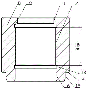
[0031] like figure 2 As shown, a support sleeve se...


PUM


Abstract

A thread bending-preventing mechanism comprises a column and a nut, wherein the column is fixed through the nut, a column rod comprises a thread section and a supporting shaft section, and the nut comprises inner threads and a supporting sleeve section. When the nut and the thread section of the column are screwed, the supporting shaft section is in clearance fit with the supporting sleeve section to form a supporting section. The supporting sleeve section of the nut restrains the supporting shaft section of the column in the radial direction to protect the thread section of the column, and the thread section of the column is prevented from being bent. In addition, by means of locating match of the supporting sleeve section and the supporting shaft section, bending of the thread section of the column is obviously prevented. An unloading groove is also formed so that the curve position of the column can be controlled flexibly.

Description

technical field [0001] The invention relates to a threaded mechanism, in particular to improving the anti-bending capability of a threaded segment of the threaded mechanism. Background technique [0002] A threaded mechanism is a commonly used fastening mechanism used to fix or support other objects. It generally includes a cylinder and a nut. The cylinder is combined with the nut through the thread on it. In the existing threaded mechanism, the cylinder and the nut basically provide tensile load through thread engagement. The axial load in the structure is all borne by the cylinder thread, and the cylindrical thread segment is inevitably stress concentrated due to material, processing and other reasons. , The axial load distribution on each screw thread is uneven, especially when applied to the support plate, the shear force acting on the cylindrical thread part when the support plate is bent and deformed is very bad, resulting in the rapid fatigue of the cylinder, and fina...

Claims


Application Information

Patent Timeline
Patent Type & Authority Patents(China)
IPC IPC(8): F16B41/00B29C45/17
Inventor 史天瑜
Owner HAITIAN PLASTICS MACHINERY GRP
Why Eureka
Try Eureka