
Drag-link mechanism of injection molding machine

A tie rod mechanism and injection molding machine technology, applied in the tie rod mechanism field, can solve the problems of tie rod fatigue, failure, badness, etc., and achieve the effect of weakening the influence of the force on the annular surface, flexible and controllable position and degree, and protecting the threaded section.

Active Publication Date: 2014-03-26
HAITIAN PLASTICS MACHINERY GRP
View PDF6 Cites 5 Cited by
  • Summary
  • Abstract
  • Description
  • Claims
  • Application Information

AI Technical Summary

Problems solved by technology

In the existing pull rod mechanism of injection molding machine, the pull rod and the nut basically provide the tensile load through thread engagement, and the axial load in the structure is all borne by the thread of the tie rod, and the threaded section of the tie rod is unavoidable due to materials, processing and other reasons. The stress is concentrated, and the distribution of axial load on each screw thread is not uniform, especially the shear force acting on the threaded part of the tie rod when the formwork is bent and deformed is very bad, resulting in the fast fatigue of the tie rod and eventually breaking and failure

Method used


Image

  • Drag-link mechanism of injection molding machine
  • Drag-link mechanism of injection molding machine
  • Drag-link mechanism of injection molding machine

Examples


Embodiment Construction

[0026] The present invention will be further described below in conjunction with the embodiments of the accompanying drawings.

[0027] Such as figure 1 As shown, the head of the tie rod 1 of the injection molding machine is provided with a threaded section 19 , and the front and rear areas adjacent to the threaded section 19 are provided with a fulcrum section 17 and a fulcrum section 18 .

[0028] An undercut 20 is also provided between the fulcrum section 17 and the threaded section 19 to facilitate processing.

[0029] The fulcrum section 17, the fulcrum section 18, the undercut 20 and the threaded section 19 are coaxial.

[0030] The pull rod 1 is also provided with an unloading groove 3 to control the bending of the pull rod 1 through its shape and position.

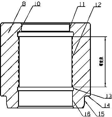
[0031] Such as figure 2 As shown, a support sleeve section 11 is arranged in front of the nut internal thread section 12 , and a support sleeve section 16 is provided behind the nut internal thread section 12 ....


PUM


Abstract

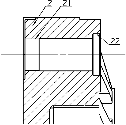
A drag-link mechanism of an injection molding machine comprises an injection molding machine head template, a drag link and a nut, wherein the drag link penetrates through the head template and is fixed by the nut; the drag link comprises a threaded section and a supporting shaft section; the nut comprises an internal thread and a supporting sleeve section; and when a threaded section formed when the nut and the drag link are fixed is screwed up, the supporting shaft section and the supporting sleeve section are in clearance fit to form a supporting section. According to the drag-link mechanism, the threaded section of the drag link is protected through the radial constraint applied by the supporting sleeve section of the nut to the supporting shaft section of the drag link, so that bending of the threaded section of the drag link is prevented; in addition, by the aid of positioned matching of the supporting sleeve section and a supporting shaft, the bending of the threaded section of the drag link is protected obviously. Besides, by the aid of positioned matching of an opening supporting sleeve of a drag link hole of the injection molding machine head template and an external supporting shaft section of a drag-link nut, the influence on annular surface stresses during template deformation is weakened, and the threaded section is protected indirectly. An unloading groove is also formed, so that the bending position of the drag link is flexible and controllable.

Description

technical field [0001] The invention relates to a tie rod mechanism of an injection molding machine, in particular to improving the anti-bending ability of the threaded section of the tie rod. Background technique [0002] The tie rod mechanism is a key mechanism to support the mold and other parts, which includes a tie rod and a nut, and the tie rod is positioned through the thread on the tie rod and the nut. In the existing pull rod mechanism of injection molding machine, the pull rod and the nut basically provide the tensile load through thread engagement, and the axial load in the structure is all borne by the thread of the tie rod, and the threaded section of the tie rod is unavoidable due to materials, processing and other reasons. The stress is concentrated, and the axial load distribution on each button thread is uneven, especially the shear force acting on the threaded part of the tie rod when the template is bent and deformed, is very bad, which leads to the fast f...

Claims


Application Information

Patent Timeline
Patent Type & Authority Applications(China)
IPC IPC(8): B29C45/17
CPCB29C45/1742
Inventor 史天瑜
Owner HAITIAN PLASTICS MACHINERY GRP
Learn More