
Booster for a hydraulic system

A technology of hydraulic system and booster device, applied in the direction of fluid pressure converter, mechanical equipment, etc., can solve the problems of insufficient use of oil, consumption, increase system volume and cost, etc., achieve convenient structure, reduce cost, Volume reduction effect

Active Publication Date: 2016-03-30
山重建机有限公司
View PDF7 Cites 1 Cited by
  • Summary
  • Abstract
  • Description
  • Claims
  • Application Information

AI Technical Summary

Problems solved by technology

[0002] In the hydraulic system, each actuator requires different pressures in different situations. After the actuators such as cylinders and hydraulic motors operate, they usually discharge low-pressure oil. If the low-pressure oil is not used, it will directly return to the oil tank. The oil is not fully utilized, especially in construction machinery with large potential energy such as excavating machinery, loading machinery and lifting equipment. Some actuators of these equipment, such as excavating arms and lifting arms, usually have Larger potential energy, the potential energy will prompt the actuators of the hydraulic system to discharge a large amount of low-pressure oil. If the low-pressure oil cannot be fully utilized, it will be consumed in vain; in addition, when the rated pressure of the system is low, individual components that require high pressure often An additional separate high-pressure pump is required to supply oil, and the additional high-pressure pump increases the volume and cost of the system

Method used


Image

  • Booster for a hydraulic system

Examples


Embodiment Construction

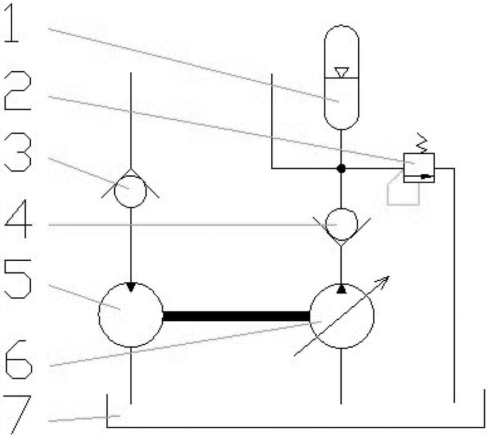
[0012] The invention discloses an energy recovery and boosting device for a hydraulic system, which includes a hydraulic motor 5, a hydraulic pump 6, an oil tank 7 and an accumulator 1. The oil flows from the pipeline to the hydraulic motor to drive the hydraulic motor to rotate; After absorbing the oil, pump the oil to the accumulator, which is characterized in that the accumulator 1 is pre-charged with a certain pressure, the output shaft of the hydraulic motor is connected with the input shaft of the hydraulic pump, and the rotation of the hydraulic motor drives the rotation of the hydraulic pump , the displacement of the hydraulic motor is greater than the displacement of the hydraulic pump, so that the low-pressure liquid flow from the pipeline drives the small-displacement hydraulic pump through the large-displacement hydraulic motor, realizing the conversion of low pressure to high pressure, and conversion to high pressure The oil is stored in the accumulator. Therefore...


PUM


Abstract

The invention provides a pressure boosting device of a hydraulic system. The pressure boosting device comprises a hydraulic motor, a hydraulic pump, an oil tank and an energy accumulator, wherein oil flows into the motor from a pipeline to drive the motor to rotate; the pump pumps the oil from the oil tank into the energy accumulator, a certain amount of pressure is inflated into the energy accumulator in advance, an output shaft of the motor is connected with an input shaft of the pump, the hydraulic motor rotates to drive the hydraulic pump to rotate, and the discharge capacity of the hydraulic motor is larger than that of the hydraulic pump so that the large discharge capacity motor drives the small discharge capacity pump to convert low-pressure oil from a pipeline into high-pressure oil to be stored in the energy accumulator. By means of the pressure boosting device of the hydraulic system, surplus energy such as potential energy in the system can be conveniently converted into hydraulic energy to be stored, and the hydraulic energy is supplied to the system when the system needs more energy, so that environment-friendly and economical effects are achieved; the stored energy can be used as a high-pressure source to provide high-pressure oil for the hydraulic system, so that addition of a single high-pressure pump is avoided, the size of the system is reduced, and costs are reduced.

Description

technical field [0001] The invention relates to a boosting device for a hydraulic system, in particular to an energy recovery boosting device for a hydraulic system which converts low pressure in the hydraulic system into a high pressure. Background technique [0002] In the hydraulic system, each actuator requires different pressures in different situations. After the actuators such as cylinders and hydraulic motors operate, they usually discharge low-pressure oil. If the low-pressure oil is not used, it will directly return to the oil tank. The oil is not fully utilized, especially in construction machinery with large potential energy such as excavating machinery, loading machinery and lifting equipment. Some actuators of these equipment, such as excavating arms and lifting arms, usually have Large potential energy, the potential energy will prompt the actuators of the hydraulic system to discharge a large amount of low-pressure oil. If the low-pressure oil cannot be fully...

Claims


Application Information

Patent Timeline
Patent Type & Authority Patents(China)
IPC IPC(8): F15B3/00
Inventor 凌在山魏敬成李晖王克车朱秀菊于海亮
Owner 山重建机有限公司
Learn More