
An RFID flexible bending adjustable antenna

An antenna and curved technology, applied in the field of RFID antennas, can solve problems such as massive cost increases, inability to realize automatic production identification, and large production line space, so as to enhance adaptability and installation convenience, and avoid structural parts, cylinders, and fixtures the additional effect of

Active Publication Date: 2018-12-04
GUANGDONG SYGOLE INTELLIGENT TECH CO LTD
View PDF1 Cites 0 Cited by
  • Summary
  • Abstract
  • Description
  • Claims
  • Application Information

AI Technical Summary

Problems solved by technology

Different applications require multiple different antennas to complete, and it is impossible to realize flexible automatic production identification, resulting in massive cost increases during distributed deployment. At the same time, the structure is very complicated. According to the distance of reading and writing, it is necessary to design complex cylinder telescopic devices and occupy The large production line space is easy to cause interference to robots, jacking mechanisms, etc. For distance and applications that need to read multiple directions, traditional antennas cannot meet

Method used


Image

  • An RFID flexible bending adjustable antenna
  • An RFID flexible bending adjustable antenna
  • An RFID flexible bending adjustable antenna

Examples


Embodiment Construction

[0022] The gist of the present invention is to overcome the deficiencies of the prior art, and provide an RFID flexible bending adjustable antenna with simple structure and low cost. The following will describe in detail with reference to the accompanying drawings in conjunction with the embodiments, so as to further explain the technical features and advantages of the present invention.

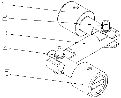
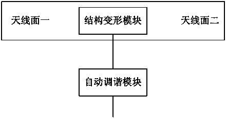
[0023] like figure 1 , 2 As shown, an RFID flexible bending adjustable antenna includes antenna one 1, antenna two 5, and an antenna structure adjustment member 3 movably connected between antenna one 1 and antenna two 5, and the antenna structure adjustment member 3 is composed of It consists of a structural deformation module and an automatic tuning module. The structural deformation module is connected to the antenna one 1 and the antenna two 5 respectively, and the automatic tuning module is connected to the structural deformation module by communication. The first antenna 1 and the se...


PUM


Abstract

The invention discloses a radio frequency identification (RFID) flexible bending type adjustable antenna. The RFID flexible bending type adjustable antenna comprises a first antenna, a second antenna and an antenna structure adjustment element, wherein the antenna structure adjustment element is movably connected between the first antenna and the second antenna and comprises a structure deformation module and an automatic tuning module, the structure deformation module is in communication connection with the first antenna and the second antenna separately, and the automatic tuning module is in communication connection with the structure deformation module. By the RFID flexible bending type adjustable antenna, the adaptability and the installation convenience of a single antenna in different application links can be greatly improved; the problem that a tool of a robot structure is required to be designed repeatedly is solved, and the antenna can be applicable to manual grapping of a robot; the problem that a large amount of antenna verification work is required when distance is changed is solved, and the antenna angle and combination can be directly configured by an adjustable module; and the cost problem is solved, the structure adjustment module and the automatic tuning module both belong to miniature and simple devices, a customized structural member at a large scale is prevented, and the addition of an air cylinder and a tool fixture is prevented.

Description

technical field [0001] The invention relates to an RFID antenna, in particular to an RFID flexible bending adjustable antenna. Background technique [0002] The RFID antenna is also called the RFID tag antenna. The RFID tag antenna is the transponder antenna of the RFID electronic tag and is a communication induction antenna. Generally, the RFID electronic tag transponder is composed of a chip. RFID tag antennas are divided into metal etching antennas, printed antennas, and copper-plated antennas due to different materials and manufacturing processes. [0003] RFID antenna manufacturing technologies mainly include etching method, coil winding method and printing antenna. Among them, RFID conductive ink printing antenna is a new technology developed. The above manufacturing methods of RFID tag antennas are respectively applicable to RFID electronic tag products of different frequencies. The low-frequency LF RFID electronic tag antenna is basically made by winding. The hig...

Claims


Application Information

Patent Timeline
Patent Type & Authority Patents(China)
IPC IPC(8): H01Q1/12H01Q1/08
CPCH01Q1/08H01Q1/084H01Q1/12
Inventor 王瑜辉张超赵朝源尹周平陈绪兵
Owner GUANGDONG SYGOLE INTELLIGENT TECH CO LTD
Learn More