Energy conversion generating device

A power generation device and energy conversion technology, applied in wind power generation, fluid pressure converters, engines, etc., can solve the problems of scattered distribution of wind turbines, inability to control the utilization efficiency of electric energy stably, and failure to satisfy the energy utilization of the masses, etc., and achieve structural design Simple and scientific, the effect of meeting the requirements of utilization

Active Publication Date: 2014-03-26
来风新能源科技(河南)有限公司
View PDF6 Cites 0 Cited by
  • Summary
  • Abstract
  • Description
  • Claims
  • Application Information

AI Technical Summary

Problems solved by technology

When wind energy is used as a kind of power energy, wind energy is often converted into electrical energy by means of wind turbines. Due to the scattered distribution of wind turbines, the existing wind turbines cannot stably control the generated electrical energy and the utilization efficiency is low. People's requirements for energy utilization

Method used


Image

  • Energy conversion generating device

Examples


specific Embodiment 1

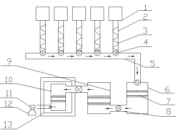
[0012] Specific embodiment 1: such as figure 1 The shown energy conversion type power generation device is characterized by comprising: a windmill 1, a small hydraulic cylinder 2, a screw auger 3, a valve 4, a hydraulic pipe 5, a large hydraulic cylinder chamber 6, a pneumatic cylinder chamber 9, and a small hydraulic cylinder chamber 10. , High-pressure pipe 8, piston 7, pressure control chamber 13, page 11, generator 12, in which windmill 1 is fixedly installed on small hydraulic cylinder 2, small hydraulic cylinder 2 is connected with hydraulic pipe 5, and one end of large hydraulic cylinder chamber 9 The other end connected to the hydraulic pipe 5 is connected to the pneumatic cylinder chamber 9 through the high-pressure pipe 8. The pneumatic cylinder chamber 9 is connected to the small hydraulic cylinder chamber 10 in the pressure control chamber 13 through the high-pressure pipe 8, and the page plate 11 is fixedly installed on the generator 12 , The small hydraulic cylind...


PUM


Abstract

The invention relates to the field of generating devices, in particular to an energy conversion generating device, which is characterized by comprising windmills, small hydraulic cylinders, helical augers, valves, a hydraulic pipeline, a large hydraulic cylinder chamber, a pneumatic cylinder chamber, a small hydraulic cylinder chamber, a high-pressure tube, pistons, a pressure control chamber, a hinge plate and a generator, wherein the windmills are fixedly arranged on the small hydraulic cylinders; the small hydraulic cylinders are connected with the hydraulic pipeline; one end of the large hydraulic cylinder chamber is connected with the hydraulic pipeline, and the other end of the large hydraulic cylinder chamber is connected with the pneumatic cylinder chamber through the high-pressure tube; the pneumatic cylinder chamber is connected with the small hydraulic cylinder chamber in the pressure control chamber through the high-pressure tube; the hinge plate is fixedly arranged on the generator; the small hydraulic cylinder chamber is formed in the pressure control chamber; the valves are arranged between the small hydraulic cylinders and the hydraulic pipeline, between the hydraulic pipeline and the large hydraulic cylinder chamber, between the large hydraulic cylinder chamber and the pneumatic cylinder chamber as well as between the pneumatic cylinder chamber and the pressure control chamber; the helical augers are arranged in the small hydraulic cylinders; the pistons are arranged in the small hydraulic cylinders, the large hydraulic cylinder chamber, the pneumatic cylinder chamber and the small hydraulic cylinder chamber.

Description

Technical field [0001] The invention relates to the field of power generation devices, in particular to an energy conversion type power generation device. Background technique [0002] Wind energy is non-fossil energy, green energy, and rich in resources. When wind energy is used as a power source, wind energy often uses wind turbines to convert wind energy into electrical energy. Due to the scattered distribution of wind turbines, the existing wind turbines cannot control the generated electrical energy stably and have low utilization efficiency. The people's requirements for energy utilization. Summary of the invention [0003] In order to overcome the above-mentioned problems, the present invention provides an energy conversion type power generation device, which is characterized by comprising: a windmill, a small hydraulic cylinder, a screw auger, a valve, a hydraulic pipe, and a large hydraulic cylinder Chamber, pneumatic cylinder chamber, small hydraulic cylinder chamber, ...

Claims


Application Information

Patent Timeline
Patent Type & Authority Applications(China)
IPC IPC(8): F03D9/00F15B3/00F03B13/00
CPCY02E10/72
Inventor 常典军何社利司龙飞
Owner 来风新能源科技(河南)有限公司
Why Eureka
Try Eureka