
Crucible used for preparing monocrystalline silicon by czochralski method

A single crystal silicon, Czochralski technology, applied in the field of crucibles, can solve the problems of long heating time, shorten the service life of the crucible, slow heating, etc., and achieve the effects of good temperature control performance, reduced sidewall thickness, and extended service life.

Inactive Publication Date: 2014-03-26
SHANGHAI JMS ELECTRONICS MATERIALS
View PDF5 Cites 10 Cited by
  • Summary
  • Abstract
  • Description
  • Claims
  • Application Information

AI Technical Summary

Problems solved by technology

When preparing silicon seed crystals, the heating device on the side of the crucible provides the heat source, causing the outer temperature of the melt to be higher than the central axis, and the temperature at the bottom of the melt to be higher than the liquid surface. Since the density of silicon material decreases with the increase of temperature, the temperature at the bottom The melt will flow upwards by buoyancy, and the preparation system will exchange heat with the heating elements on both sides through the graphite crucible wall, but the heat dissipation effect of the arc-shaped graphite crucible wall is not ideal
Due to the simple structure of the existing graphite crucible, there are disadvantages such as low heat transfer efficiency, slow heating, long heating time, and high energy consumption; in addition, gas will be generated during the preparation of silicon, and the gas will condense into liquid after being cooled and flow along the arc. The shaped bottom surface flows to the bottom support of the graphite crucible, and finally causes the graphite crucible to stick to the bottom support
Reduce the service life of the crucible, which is not conducive to the production of single crystal silicon

Method used


Image

  • Crucible used for preparing monocrystalline silicon by czochralski method
  • Crucible used for preparing monocrystalline silicon by czochralski method
  • Crucible used for preparing monocrystalline silicon by czochralski method

Examples


Embodiment 1

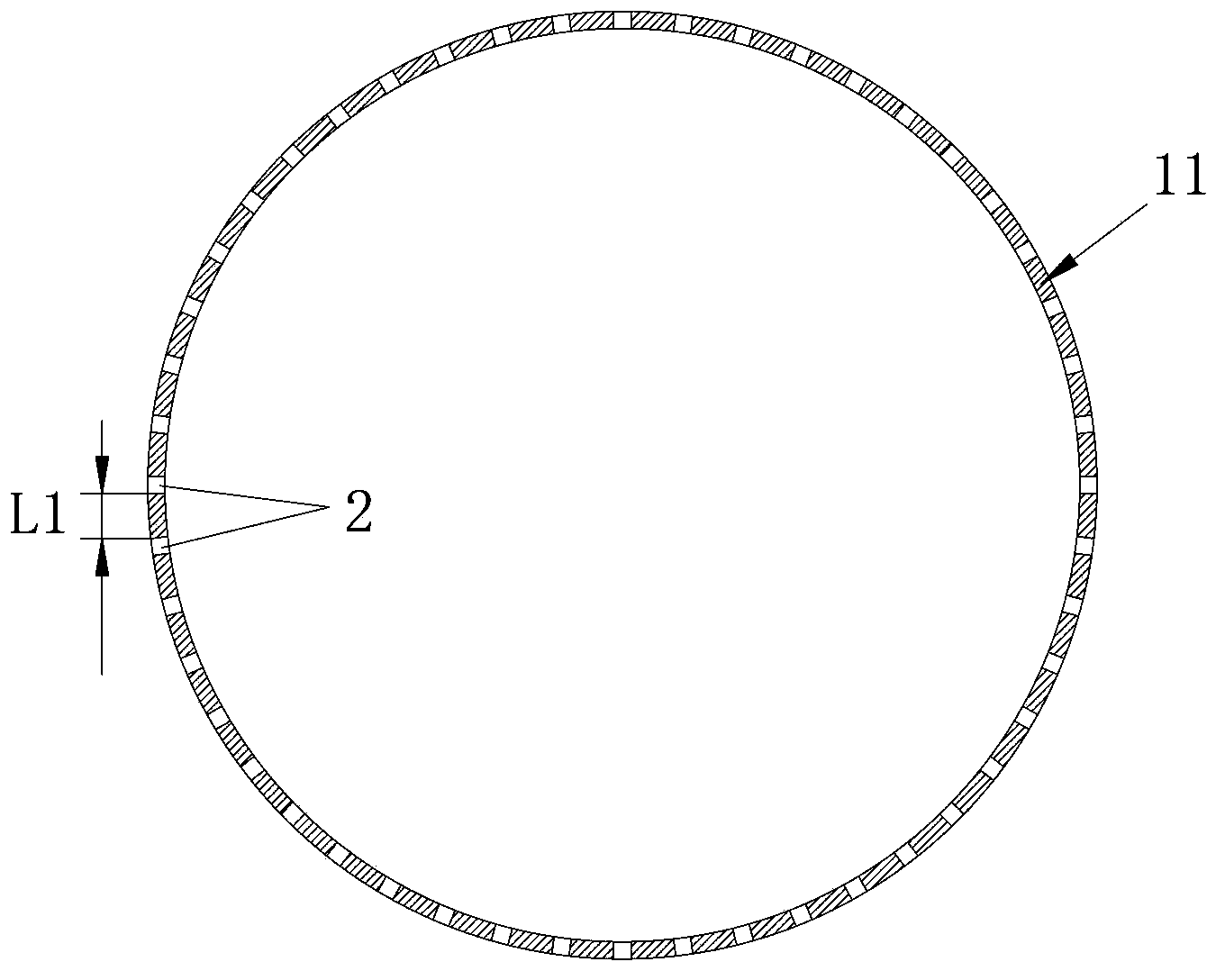
[0033] The diameter d of the heat conduction hole of the crucible side wall 11 of the carbon-carbon composite material described in this embodiment is 8-15 mm; the distance L1 between the boundaries of two adjacent heat conduction holes 2 is 30-50 mm.

Embodiment 2

[0035] The diameter d of the heat conduction hole of the crucible side wall 11 of the carbon-carbon composite material described in this embodiment is 10 mm, and the distance L1 between the boundaries of two adjacent heat conduction holes 2 is 50 mm.

Embodiment 3

[0037] The crucible described in this embodiment is a two-stage crucible structure (not shown in the figure), including the side wall of the upper layer of carbon-carbon composite material and the bottom of the lower layer of graphite material, and the heat conduction holes are arranged on the side wall .


PUM

PropertyMeasurementUnit
diameteraaaaaaaaaa
thicknessaaaaaaaaaa

Abstract

The invention discloses a crucible used for preparing monocrystalline silicon by a czochralski method. The crucible comprises a crucible main body which is composed of a bottom and a side wall, wherein the crucible is of a sectional type crucible structure; the crucible main body is at least divided into two sections from top to bottom according to difference of materials; the crucible main body comprises an upper-layer side wall made of a carbon-carbon composite material and a lower-layer bottom made of a graphite material, wherein a plurality of heat-conducting holes are uniformly distributed on the side wall; the diameter of the heat-conducting holes is 5mm-20mm; distance between borders of the heat-conducting holes is 10mm-50mm according to different pore densities; an area, which is uniformly distributed with the heat-conducting holes, on the side wall is 2cm-6cm from the side wall; the width of the side wall in the downwards vertical direction is 16cm-25cm; the inner side surface of the side wall of the area is parallel to a center shaft of the crucible. The crucible disclosed by the invention has characteristics of good heat conductivity, good temperature control, long service life and great loading amount.

Description

technical field [0001] The invention relates to a crucible, in particular to a crucible used for preparing single crystal silicon by Czochralski method. Background technique [0002] At present, there are mainly two technologies for preparing single crystal silicon. According to the different crystal growth methods, they can be divided into zone melting single crystal silicon and Czochralski single crystal silicon. Czochralski monocrystalline silicon is mainly used in microelectronic integrated circuits and solar cells, and is the main body of monocrystalline silicon. [0003] The Czochralski method uses the driving principle of condensation and crystallization of the melt. At the solid-liquid interface, the phase change from liquid to solid will occur as the temperature of the melt drops. In order to grow single crystal silicon rods with qualified quality (silicon single crystal resistivity, oxygen content and oxygen concentration distribution, carbon content, metal impuri...

Claims


Application Information

Patent Timeline
Patent Type & Authority Applications(China)
IPC IPC(8): C30B15/10C30B29/06
Inventor 周俭李德建陈昌林陈锐陈剑春付雁清薛东李福龙
Owner SHANGHAI JMS ELECTRONICS MATERIALS
Learn More