
Thorough cut sludge elutriation separator stirring device

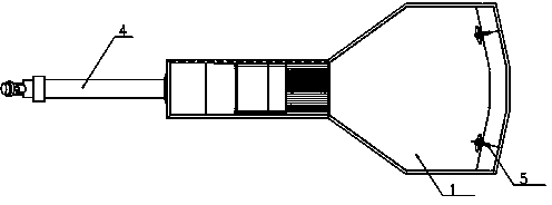
A technology of stirring device and communicating sludge, which is applied in the field of mixing device of mud washing and separating machine, can solve the problems of overload of motor, easy wear of paddles, high sand and gravel content, etc., so as to prolong the service life and seal The effect of good effect and simple sealing operation

Inactive Publication Date: 2014-03-26
SHANGHAI SUS ENVIRONMENT
View PDF5 Cites 3 Cited by
  • Summary
  • Abstract
  • Description
  • Claims
  • Application Information

AI Technical Summary

Problems solved by technology

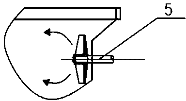
[0003] However, the mechanical agitation elutriation device has the following disadvantages: 1) The agitator paddle is easily entangled with larger solid waste (such as plastic products) during the agitation process, causing overload of the motor, causing shutdown or even burning the motor; 2) There is a lot of sand and gravel in the ditch sludge, and the blades are easy to wear during rotation; 3) A sealing device needs to be installed at the connection position of the mixing paddle in the sludge tank. Long-term operation will easily cause wear of the sealing ring, and water seepage and leakage will occur

Method used


Image

  • Thorough cut sludge elutriation separator stirring device
  • Thorough cut sludge elutriation separator stirring device
  • Thorough cut sludge elutriation separator stirring device

Examples


Embodiment Construction

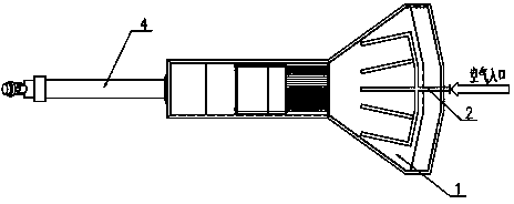
[0018] like figure 2 As shown, the structure diagram of the ditch sludge elutriation separator of the present invention is to change the existing mechanical agitation device into an air agitation device, which consists of a sludge tank 1, a microporous aeration device 2, a slag removal machine 3. The grit settling conveyor 4 is composed; the inlet of the aeration device pipeline is arranged at the front end of the sludge tank 1, and the aeration pipeline in the sludge tank is laid flat on the bottom of the sludge tank, and the installation direction is the same as the flow direction of the cleaning water consistent, such as Figure 4 As shown, prevent the pipeline from blocking the sludge.

[0019] The present invention adopts the aeration air flotation method, and adopts a blower and a microporous aeration device 2 . The blower (not shown in the figure) sends the air to the microporous aeration device, and the air outlet is located under the microporous aeration pipe to pr...


PUM


Abstract

The invention relates to improvement of a thorough cut sludge elutriation separator stirring device, in particular to the thorough cut sludge elutriation separator stirring device which comprises a sludge tank, an aerating apparatus, a slag conveyor and a settling sand conveyor, wherein the pipeline inlet of the aerating apparatus is formed in the front end of the sludge tank; an aerating pipeline of the sludge tank is paved at the bottom of the sludge tank, and the arrangement direction of the aerating pipeline is the same as the flow direction of rinsing water. The experiment result shows that an air type stirring thorough cut sludge elutriation separator disclosed by the invention is obviously better than the existing mechanical stirring thorough cut sludge elutriation separator in COD and the removal rate of hot igloss rate.

Description

technical field [0001] The invention relates to the improvement of the stirring device of the elutriation and separator of ditch sludge. Background technique [0002] The agitation device of the channel sludge elutriation separator whose publication number is CN101838089B and CN201120132375 adopts a mechanical agitation type. figure 1 , image 3 and Figure 5 . In the figure, the ditch sludge elutriation separator is composed of a sludge tank 1, a slag removal machine 3, a grit conveyor 4 and a stirring paddle 5, and a wave wheel paddle type stirring paddle is installed in the front section of the sludge tank. The stirring paddle rotates continuously, and the nozzle continuously sprays high-pressure cleaning water. The hydraulic and mechanical forces generated by the two jointly push the sludge to move to the rear of the sludge tank. The scum floats on the water surface of the sludge tank, the heavy grit sinks to the bottom of the sludge tank, and the decayed organic mat...

Claims


Application Information

Patent Timeline
Patent Type & Authority Applications(China)
IPC IPC(8): C02F11/00
Inventor 龙吉生朱晓平白力石剑菁瞿兆舟冯淋淋王湘徽段广杰陆锟董文芳
Owner SHANGHAI SUS ENVIRONMENT
Learn More