Vertical-flow self-aeration annular artificial wetland system

A constructed wetland system and automatic oxygenation technology, applied in sustainable biological treatment, energy wastewater treatment, water/sludge/sewage treatment, etc., can solve the problems of easy clogging of openings, no environmental conditions, and increased concentration. Achieve the effect of controlling mosquito breeding, reducing infrastructure investment and saving water resources

Inactive Publication Date: 2014-03-26
NANJING UNIV
View PDF3 Cites 5 Cited by
  • Summary
  • Abstract
  • Description
  • Claims
  • Application Information

AI Technical Summary

Problems solved by technology

[0006] 1. The ventilation pipe is self-flowing air ventilation, and the air transfer efficiency is not high; and the laying of multi-layer ventilation pipes increases the infrastructure investment of the wetland system
[0007] 2. The method of wind energy oxygenation is greatly restricted by region and climate, resulting in unstable treatment effect of wetland system
[0008] 3. None of the three aeration methods create the optimal aerobic and anaerobic environmental conditions required for nitrification and denitrification reactions, resulting in NO in wetland effluent 3 ― concentration increases, the removal rate of nitrogen decreases
[0009] 4. The three aeration methods are to directly bury the open-hole ventilation pipe in the matrix of the wetland system, and fine sand and gravel can easily block the opening of the ventilation pipe

Method used


Image

  • Vertical-flow self-aeration annular artificial wetland system
  • Vertical-flow self-aeration annular artificial wetland system
  • Vertical-flow self-aeration annular artificial wetland system

Examples


Embodiment

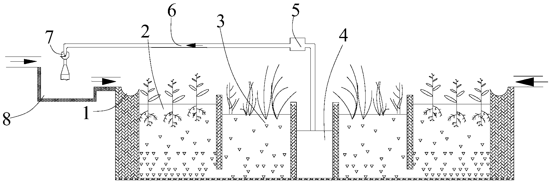
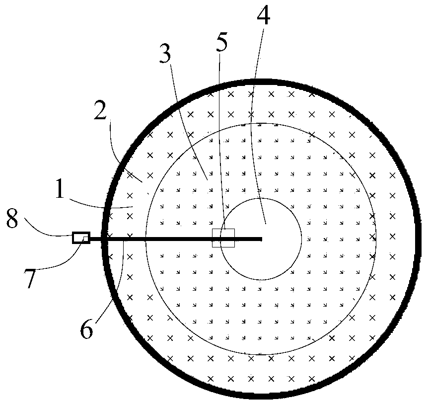
[0032] Such as figure 1 As shown, the vertical flow automatic oxygenation constructed wetland system includes a diversion groove 1, a downward flow annular pool 2, an upward flow annular pool 3, a collecting pool 4, a return pump 5, a loop pipeline 6, an automatic oxygenation return device 7 and a shallow Adjusting pool 8. The diversion groove 1 is arranged on the outer wall of the downstream annular pool, and the upstream annular pool is located inside the downstream annular pool. Both the downflow annular pool and the upflow annular pool adopt circular circulation pools, and a partition wall is arranged between them and communicated through a gap at the bottom of the partition wall.

[0033] Both the downward flow annular pool and the upward flow annular pool are equipped with fillers. The downward flow annular pool is filled with gravel layer, ceramsite layer and cinder layer in sequence from bottom to top, and the top layer is set with a semi-clay layer as a plant substrate ...


PUM


Abstract

The invention provides a vertical-flow self-aeration annular artificial wetland system which comprises a diversion groove, a downstream annular pool, an upstream annular pool, a water collection pool, a reflux pump, a self-aeration reflux device and a shallow regulating pool, wherein the diversion groove is positioned on the outer wall of downstream annular pool; the upstream annular pool is positioned on the inner side of the downstream annular pool; the water collection pool is arranged on the inner side of the upstream annular pool; the water inlet of the reflux pump is connected with the water collection pool; the water outlet of the reflux pump is connected with the self-aeration reflux device arranged above the shallow regulating pool, inside the shallow regulating pool or on the inner wall of the shallow regulating pool through a reflux pipeline; the sewage outlet of the shallow regulating pool is communicated with the diversion groove through a pipeline or a water channel. The vertical-flow self-aeration annular artificial wetland system has the advantages that the contact time of sewage and air is prolonged, so that the dissolved oxygen in the sewage is increased, the purifying effect of sewage controlling is improved, capital investment is reduced, fly breeding is effectively controlled, effluent is collected and reused as reclaimed water, and water resources are saved effectively.

Description

Technical field [0001] The invention belongs to the technical field of environmental engineering sewage treatment, and more specifically relates to a simple, efficient and uniform water distribution and oxygenation system of a vertical flow automatic oxygenation annular constructed wetland system, which is suitable for domestic sewage, contaminated surface water, non-point source sewage, and relatively high composition. The treatment of complex wastewater is also suitable for domestic sewage and sewage treatment with large temperature differences. Background technique [0002] Constructed wetland is a new type of wastewater treatment technology developed in the 1970s and 1980s, due to its high efficiency, low investment, and low transfer cost technology. It has been widely used in the treatment of oily wastewater, domestic sewage, sewage from breeding farms, and lake pollution prevention and control. [0003] At present, according to the different ways of wastewater runoff, the ty...

Claims


Application Information

Patent Timeline
Patent Type & Authority Applications(China)
IPC IPC(8): C02F3/32
CPCY02W10/10Y02W10/33
Inventor 孙亚兵何东侯吉妃辛路张梦怡李舜斌
Owner NANJING UNIV
Why Eureka
Try Eureka