
Nozzle Cleaning Fixture

A technology for cleaning jigs and jigs, applied in cleaning methods and utensils, cleaning methods using gas flow, chemical instruments and methods, etc. Good maintenance, avoid personnel waste and excessive time investment, optimize the effect of maintenance process

Inactive Publication Date: 2016-12-21
上海万得凯实业有限公司
View PDF7 Cites 0 Cited by
  • Summary
  • Abstract
  • Description
  • Claims
  • Application Information

AI Technical Summary

Problems solved by technology

[0012] The technical problem to be solved by the present invention is to provide a nozzle cleaning fixture for overcoming the cumbersome cleaning and maintenance procedures of surface mount technology (SMT) nozzles in the prior art, which consumes time and energy and poor cleaning effect.

Method used


Image

  • Nozzle Cleaning Fixture
  • Nozzle Cleaning Fixture

Examples


Embodiment Construction

[0027] Embodiments of the present invention will be described with reference to the accompanying drawings. In the drawings of the specification, elements having similar structures or functions will be denoted by the same element symbols. The drawings are only for the convenience of illustrating various embodiments of the present invention, and are not intended to describe the present invention exhaustively, nor limit the scope of the present invention.

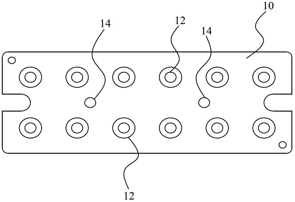
[0028] figure 1 The schematic structure of the base of the nozzle cleaning jig under a specific embodiment of the present invention is shown. In this embodiment, the nozzle cleaning jig includes a base 10 and a cover plate 20 (see figure 2 ), the base 10 is provided with a plurality of nozzle cleaners. The nozzle cleaner includes a cylindrical nozzle hole 12 for inserting the nozzle and cleaning it. Those skilled in the art can understand that the form of the nozzle cleaner is not limited, and can also be other structures ...


PUM


Abstract

The invention discloses a suction nozzle cleaning jig which comprises a base and a cover plate. The base is provided with a plurality of suction nozzle cleaning devices, the cover plate is provided with a plurality of through holes corresponding to the suction nozzle cleaning devices. By means of the suction nozzle cleaning jig, an existing suction nozzle cleaning mode can be changed, the number of cleaned objects and cleaning quality can be improved, equipment is better maintained, large personnel waste and time investment are avoided, the maintenance process is optimized, and accordingly cost is reduced.

Description

technical field [0001] The invention relates to a printed circuit board manufacturing equipment, in particular to a suction nozzle cleaning jig. Background technique [0002] With the wide popularization of various electronic devices, surface mount technology (Surface Mounted Technology "SMT") has been more and more widely used. As a new generation of electronic assembly technology, SMT has penetrated into various fields. SMT products have the advantages of compact structure, small size, vibration resistance, impact resistance, good high-frequency characteristics, and high production efficiency. [0003] SMT has occupied a leading position in the circuit board assembly process, and is currently the most popular technology and process in the electronic assembly industry. [0004] In the SMT industry, every production line must face the problem of equipment maintenance. For example, the SMT nozzles on the SMT production line are consumables and have high precision requiremen...

Claims


Application Information

Patent Timeline
Patent Type & Authority Patents(China)
IPC IPC(8): B08B5/02
CPCB08B5/02
Inventor 徐永
Owner 上海万得凯实业有限公司
Learn More