
Power converter

A power conversion device and power technology, applied in the output power conversion device, electric traction, electric/hybrid and other directions, can solve problems such as the adverse effect of long-term reliability of the circuit, and achieve suppression of high-frequency surge and temperature rise. , the effect of improving the inhibitory effect

Inactive Publication Date: 2014-03-19
SUMITOMO HEAVY IND LTD
View PDF7 Cites 6 Cited by
  • Summary
  • Abstract
  • Description
  • Claims
  • Application Information

AI Technical Summary

Problems solved by technology

In the structure of Patent Document 1, the snubber circuit is constructed using large-capacity, that is, large and heavy circuit components, and they are fastened to the bus bars, so vibration may adversely affect the long-term reliability of the circuit

Method used


Image

  • Power converter
  • Power converter
  • Power converter

Examples


Embodiment Construction

[0040] Hereinafter, the present invention will be described based on preferred embodiments with reference to the accompanying drawings. The same or equivalent constituents, members, and processes shown in each drawing are given the same reference numerals, and repeated explanations are omitted as appropriate. In addition, the embodiment does not limit the present invention but is an example, and all the features described in the embodiment and combinations thereof do not necessarily constitute the essence of the invention.

[0041] In this specification, the so-called "the state in which part A is connected to part B" includes not only the case where part A and part B are physically and directly connected, but also the passage between part A and part B that does not substantially affect their electrical connection state. or other components that do not impair the functions and effects obtained through their combination are indirectly connected.

[0042] Similarly, the so-call...


PUM


Abstract

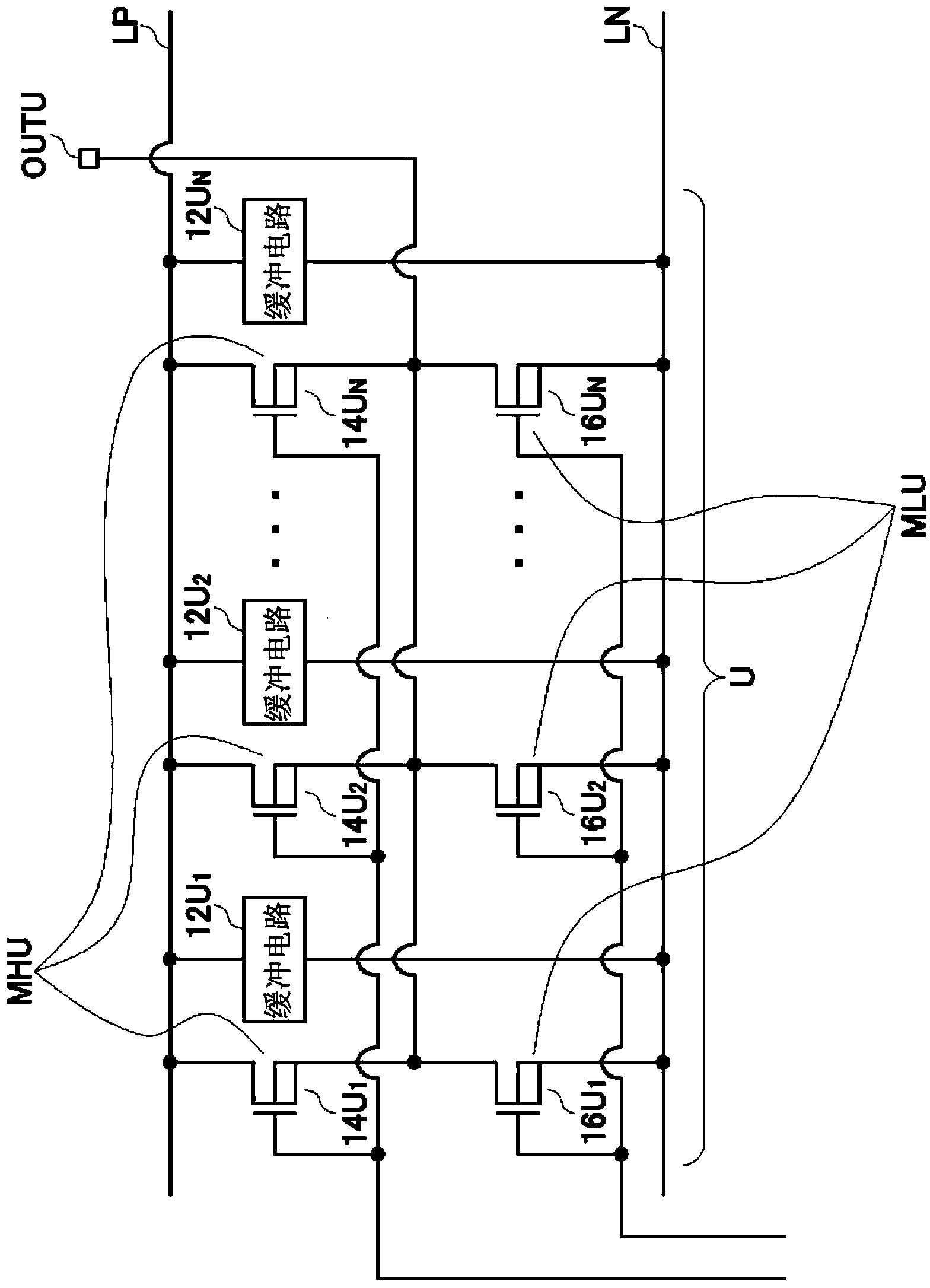
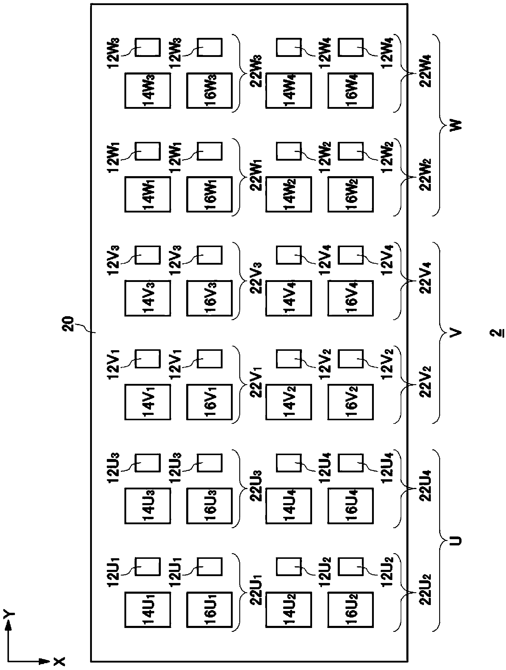
A high-side transistor (MHU) is provided between an output terminal (OUTU) of the corresponding phase and an upper power line (LP), and includes N (N an integer 2 or greater) electrically parallel high-side transistor units (14U1-N). A low-side transistor (MLU) is provided between the output terminal (OUTU) of the corresponding phase and a lower power line (LN), and includes N electrically parallel low-side transistor units (16U1-N). Snubber circuits (12) are provided for each pair consisting of one high-side transistor unit (14) and the corresponding one low-side transistor unit (16). The high-side transistor (MHU), the low-side transistor (MLU) and the n snubber circuits (12U1-N) are mounted on a metal base substrate.

Description

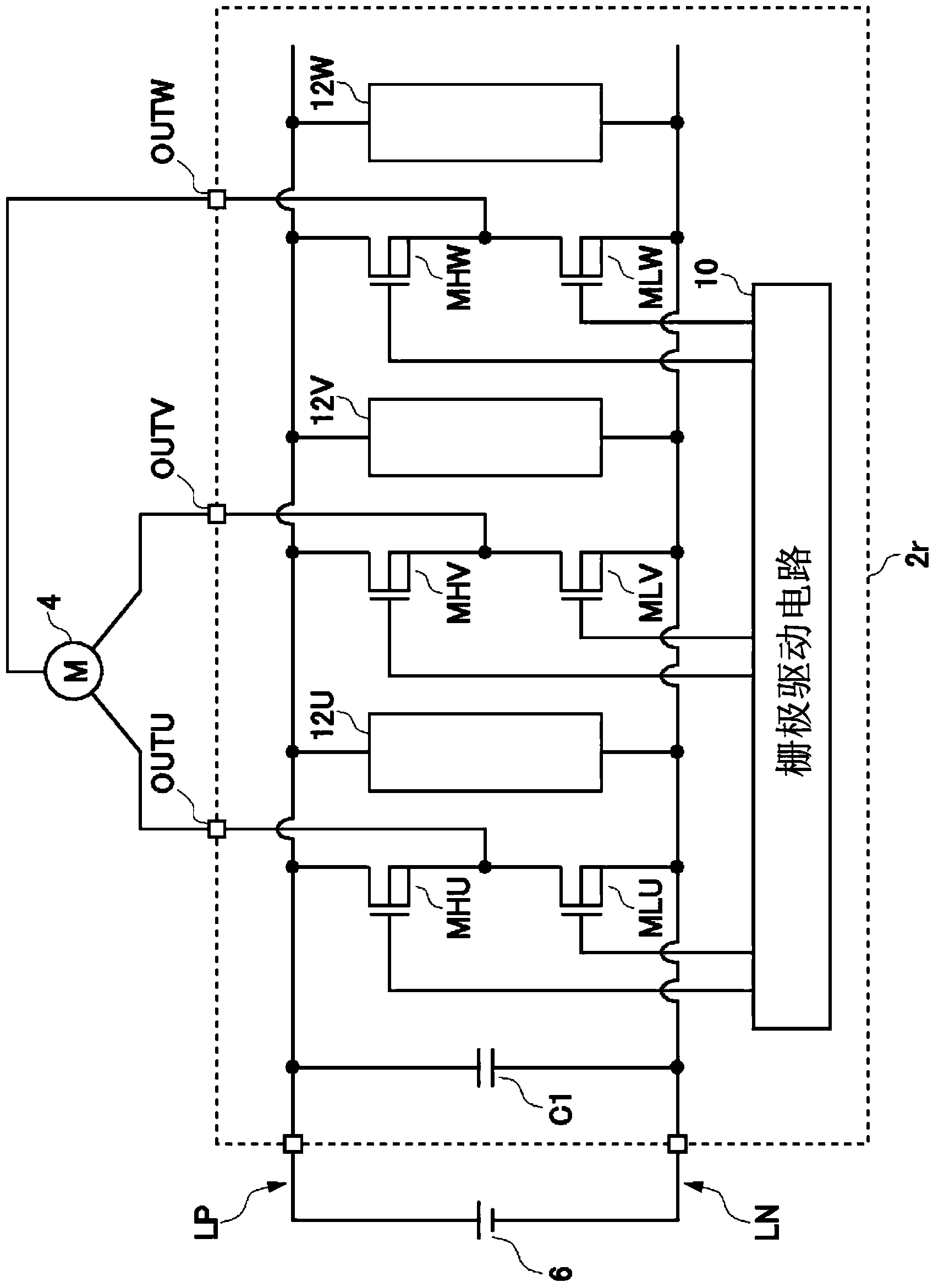
technical field [0001] The present invention relates to a power conversion device. Background technique [0002] figure 1 It is a circuit diagram showing the configuration of a general power conversion device (inverter) 2 . The power conversion device 2 is used to drive a load 4 such as a motor. The power conversion device 2 includes: high-side transistors MH (U to W) and low-side transistors ML (U to W) respectively provided in U, V, and W phases; high-side transistors MH (U to W) for each phase and a gate drive circuit 10 for driving the low-side transistor ML (U to W); and a buffer circuit 12 (U to W) provided in each phase. [0003] When a large current is supplied to the load, large-capacity power transistors are used as the high-side transistor MH and the low-side transistor ML. If noise is applied to a large-capacity power transistor, the reliability of the circuit may be impaired. Therefore, a large snubber circuit is required to prevent this. [0004] Patent Do...

Claims


Application Information

Patent Timeline
Patent Type & Authority Applications(China)
IPC IPC(8): H02M7/5387B60L9/18
CPCB60L2200/42B60L11/1803H02M7/003Y02P90/60B60L50/51Y02T10/70
Inventor 田坂泰久君岛健一
Owner SUMITOMO HEAVY IND LTD
Learn More